
A connection structure between a hydraulic cylinder piston rod and a load

A connection structure and hydraulic cylinder technology, applied in the direction of fluid pressure actuators, etc., can solve the problems of hydraulic system dynamic performance deterioration, increased clearance, and aggravated mechanism damage, so as to increase stability and reliability, reduce heat, The effect of reducing mechanical wear

Active Publication Date: 2020-06-16
HARBIN ENG UNIV
View PDF9 Cites 0 Cited by
  • Summary
  • Abstract
  • Description
  • Claims
  • Application Information

AI Technical Summary

Problems solved by technology

When the system is in the running state, due to the gap in the hinge connection, the ball joint bearing and the shaft will collide when they are in contact, which will cause noise and vibration in the system, which will aggravate the damage to the mechanism and reduce the working efficiency of the system; due to the gap. The impact force will increase the wear between the system components, thereby further increasing the clearance
[0003] The non-linearity of the gap between the piston rod of the hydraulic cylinder and the load connection hinge will cause the dynamic performance of the hydraulic system to deteriorate, increase the overshoot, increase the steady-state error, cause a response lag, and make the system non-linear, which in turn will lead to a delay in the start of the load , low-speed crawling, limit cycle oscillation, etc.

Method used


Image

  • A connection structure between a hydraulic cylinder piston rod and a load
  • A connection structure between a hydraulic cylinder piston rod and a load
  • A connection structure between a hydraulic cylinder piston rod and a load

Examples


Embodiment Construction

[0015] The present invention will be further described in detail below in conjunction with the accompanying drawings and specific embodiments.

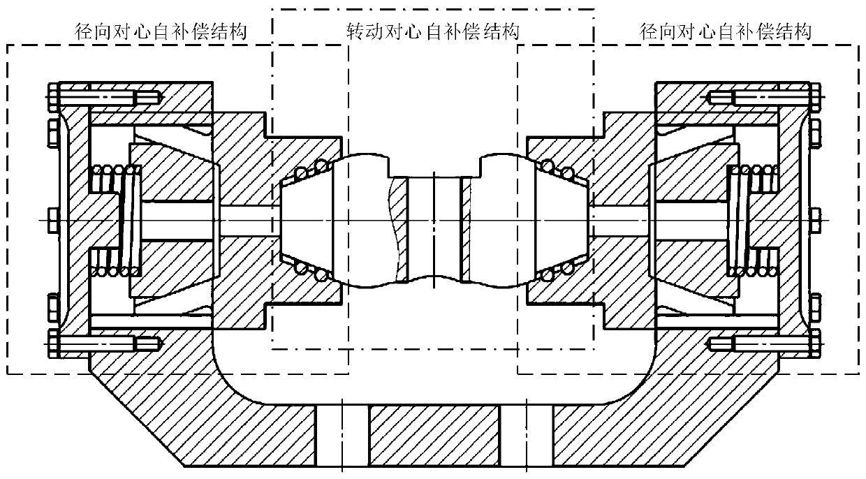
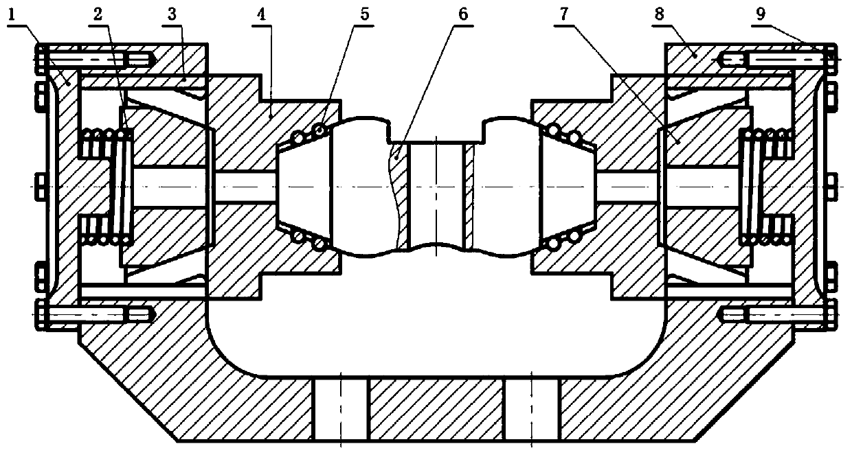
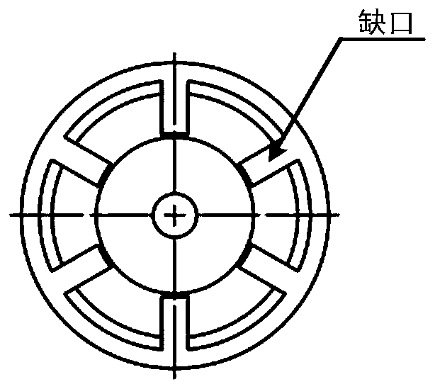
[0016] combine Figure 1~3b , the present invention is mainly composed of two parts: a radial centering self-compensation structure and a steering centering self-compensation structure. The radial centering structure is mainly composed of gland 1, compression spring 2, open bushing 3, self-compensating parts 4, expansion block 7, external parts 8, and hexagonal bolts 9; the steering centering self-compensating structure is mainly composed of self-compensating Part 4, rolling body 5, and hydraulic cylinder connecting shaft 6 are composed. The gland 1 is connected to the external member 8 through eight hexagonal bolts 9 evenly arranged, and the bottom of the external member 8 is arranged with four threaded holes symmetrically distributed to connect with the load end; the compression spring 8 is nested on the gland 1 and tightened by ex...


PUM


Abstract

The invention provides a connection structure between a piston rod of a hydraulic cylinder and a load. A radial centering self-compensation structure portion comprises an outer connection piece, glands arranged at the two ends of the outer connection piece, two open linings arranged in the outer connection piece and two self-compensation parts arranged in the open linings, wherein the two self-compensation parts are oppositely arranged, the end, in contact with the corresponding open lining, of each self-compensation part is provided with a matching conical face with a gap, the other end of each self-compensation part is provided with an inner conical face with a ball groove, the matching conical face with a gap of each self-compensation part is internally provided with an expansion ejection block, and a compression spring is arranged between each expansion ejection block and the corresponding gland. A steering centering self-compensation structure comprises a hydraulic cylinder connection shaft and a rolling body. The two ends of the hydraulic cylinder connection shaft are provided with outer conical faces matched with the inner conical faces with the ball grooves. The connectionstructure between the piston rod of the hydraulic cylinder and the load eliminates a connection gap existing between the piston rod of the hydraulic cylinder and the load in traditional hinged connection.

Description

technical field [0001] The invention relates to a connection structure between a piston rod of a hydraulic cylinder and a load, which can replace the traditional hinge connection mode, avoid non-linear gaps, and can be applied to the connection between piston rods of various hydraulic cylinders and loads. Background technique [0002] The piston rod of the hydraulic cylinder and the load are generally connected by a hinge. This connection structure often has a large movement gap. There are two specific places: the gap between the connecting shaft and the ball hinge bushing and the gap between the connecting shaft and the lug seat. Clearance. When the system is in the running state, due to the gap in the hinge connection, the ball joint bearing and the shaft will collide when they are in contact, which will cause noise and vibration in the system, which will aggravate the damage to the mechanism and reduce the working efficiency of the system; due to the gap. The impact forc...

Claims


Application Information

Patent Timeline
Patent Type & Authority Patents(China)
IPC IPC(8): F15B15/08F15B15/20
CPCF15B15/08F15B15/20
Inventor 姚建均赵月王佳奇盛唐余洁苗炳义李梦芊麦万庚
Owner HARBIN ENG UNIV
Learn More