Stirring barrel for stirring vehicle and stirring vehicle

A mixing drum and mixer truck technology, which is applied to cement mixing devices, clay preparation devices, chemical instruments and methods, etc., can solve the problems of slow feeding speed, high height of the mixer truck, unfavorable mixer truck registration, etc., and achieve an improvement The effect of increasing the loading capacity

Pending Publication Date: 2019-08-20
SANY SPECIAL PURPOSE VEHICLE CO LTD
View PDF0 Cites 1 Cited by
  • Summary
  • Abstract
  • Description
  • Claims
  • Application Information

AI Technical Summary

Problems solved by technology

Adjusting the diameter of the feeding small cone to increase the loading capacity will lead to slow feeding speed; increasing the inclination angle will make the height of the mixer truck too high, which is not conducive to the registration of the mixer truck

Method used


Image

  • Stirring barrel for stirring vehicle and stirring vehicle
  • Stirring barrel for stirring vehicle and stirring vehicle
  • Stirring barrel for stirring vehicle and stirring vehicle

Examples


Embodiment 1

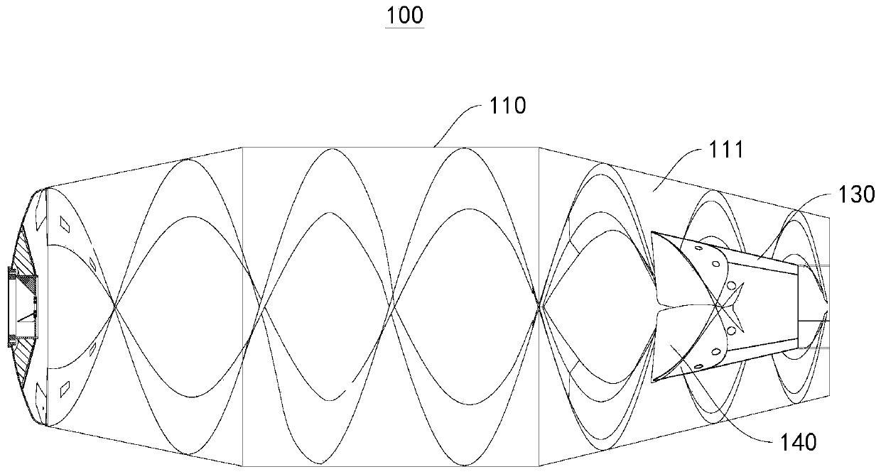
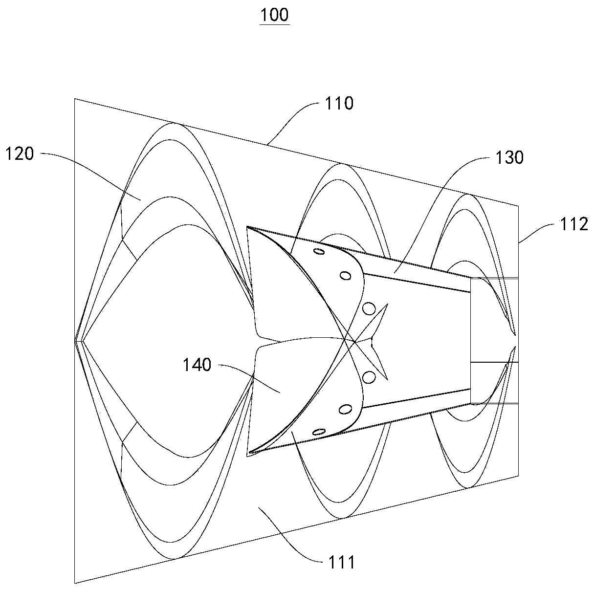
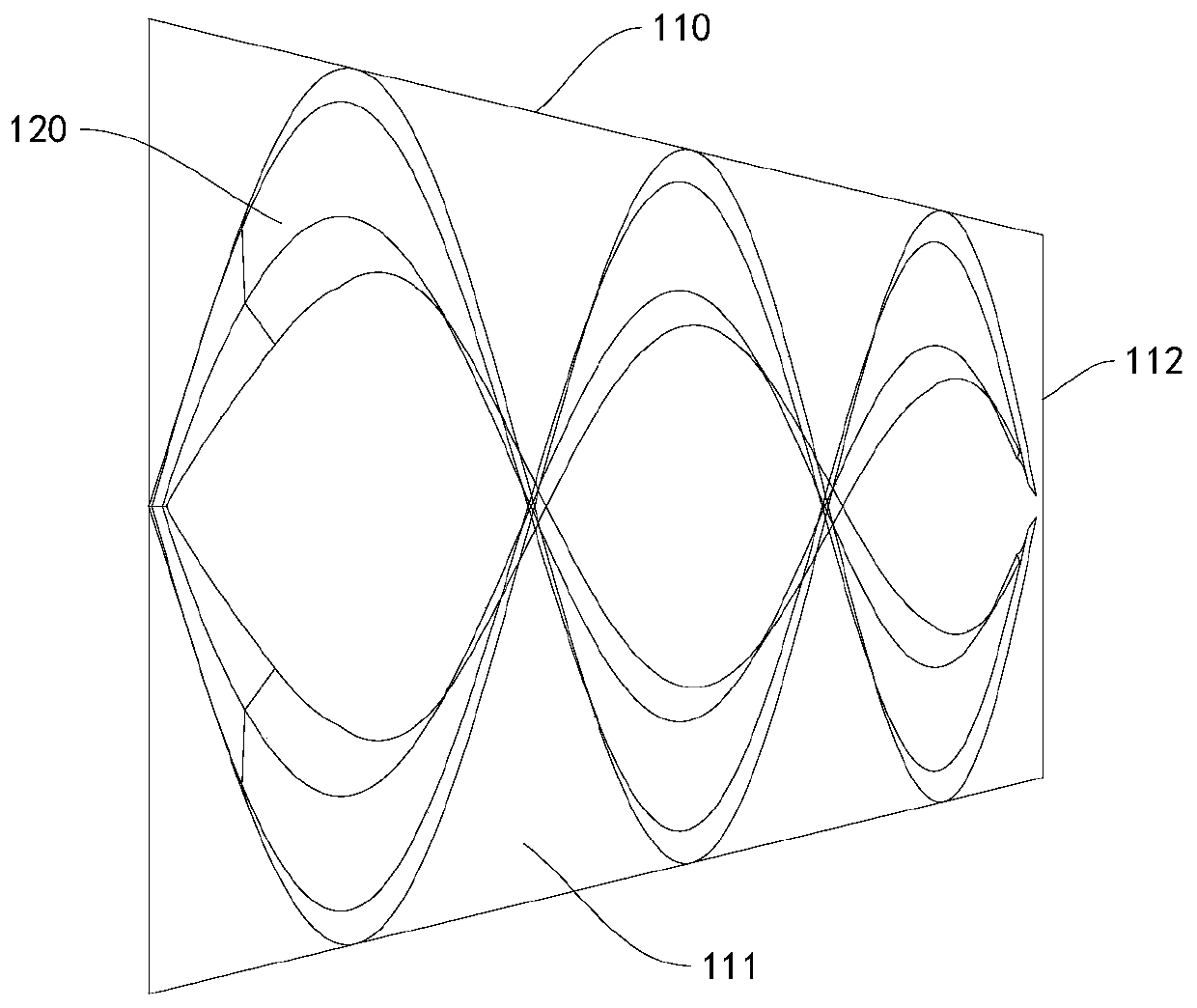
[0033] This embodiment provides a mixing drum 100 for a mixer truck, please refer to figure 1 , figure 2 , image 3 , Figure 4 as well as Figure 5 , comprising a barrel body 110 and a feed cone 130 positioned at the rear end of the barrel body 110, a discharge opening 112 is formed between the inner surface of the rear end of the barrel body 110 and the outer surface of the feed cone 130, and the inner wall of the barrel body 110 is provided with a stirring blade 120 , the inner wall of the small feeding cone 130 is provided with a small cone blade 140 , and the rotation direction of the small cone blade 140 is the same as that of the stirring blade 120 .

[0034] The opening of the feeding small cone 130 rear end is the feed inlet of the mixing drum. Therefore, the structure of the feeding small cone 130 is closely related to the feed rate of the mixing drum. In the technical solution of the present invention, the inner wall of the feeding small cone 130 Small cone bla...

Embodiment 2

[0063] This embodiment provides a mixer truck 200, please refer to Image 6 , this mixer truck 200 includes a chassis and the mixer drum 100 for a mixer truck provided in the first embodiment.

[0064] The chassis is provided with a front assembly and a backstage assembly along the length direction. The front assembly is provided with a reducer 220, and the output shaft of the reducer 220 is connected with the spherical crown 210 of the mixing drum; The rear cone of the vehicle mixer 100 is provided with a raceway 240 that cooperates with the supporting wheel 230 , and the rear cone of the mixer truck 100 is rotatably supported on the background assembly through the cooperation of the supporting wheel 230 and the raceway 240 .

[0065] When working, use the speed reducer 220 to drive the mixing drum to rotate, and the supporting wheel 230 and the raceway 240 cooperate to keep the mixing drum rotating, and due to the existence of the small cone blade 140, the mixer truck 200 ca...


PUM


Abstract

The invention provides a stirring barrel for a stirring vehicle and the stirring vehicle, and relates to the technical field of engineering vehicles. The stirring barrel for the stirring vehicle comprises a barrel body and a feeding small cone positioned at the rear end of the barrel body, a discharging opening is formed between the inner surface of the rear end of the barrel body and the outer surface of the feeding small cone, and stirring blades are arranged on the inner wall of the barrel body. The stirring barrel for the stirring vehicle is characterized in that small cone blades are arranged on the inner wall of the feeding small cone, and the rotation direction of the small cone blades are the same as the rotation direction of the stirring blades. According to the stirring barrel for the stirring vehicle and the stirring vehicle, the materials can be prevented from overflowing in the transportation process under the condition that rapid feeding and discharging are guaranteed.

Description

technical field [0001] The invention relates to the technical field of engineering vehicles, in particular to a mixer drum for a mixer truck and a mixer truck including the mixer drum for a mixer truck. Background technique [0002] At present, most of the domestic mixer trucks increase the loading by adjusting the diameter and inclination of the small feeding cone, and some enterprises make the feeding diameter of the small feeding cone smaller for lifting loading. Adjusting the caliber of the small feed cone to increase the loading capacity will result in slow feed speed; increasing the inclination angle will make the height of the mixer truck too high, which is not conducive to the mixer truck to be licensed. [0003] Therefore, for those skilled in the art, how to provide a mixing drum for a mixer truck, which can effectively control the overflow of concrete under the premise of ensuring the lifting load of the mixer truck, and try not to affect the feeding Speed ​​and ...

Claims


Application Information

Patent Timeline
IPC IPC(8): B28C5/42
CPCB28C5/4203B28C5/4268
Inventor 刘斌李琪琪傅方方
Owner SANY SPECIAL PURPOSE VEHICLE CO LTD
Why Eureka
Try Eureka