
fixed headrest structure

A technology for fixing the head and the head, which is applied in the field of medical rehabilitation equipment and can solve problems such as the inability to adjust the patient's head

Active Publication Date: 2021-03-19
FOURTH MILITARY MEDICAL UNIVERSITY
View PDF1 Cites 0 Cited by
  • Summary
  • Abstract
  • Description
  • Claims
  • Application Information

AI Technical Summary

Problems solved by technology

[0006] The main purpose of the present invention is to provide a fixed headrest structure to at least solve the problem in the prior art that the patient's head cannot be adjusted to a suitable angle according to the specific operation situation of the patient when the patient is in a supine state after the flap transplantation operation. question

Method used


Image

  • fixed headrest structure
  • fixed headrest structure
  • fixed headrest structure

Examples

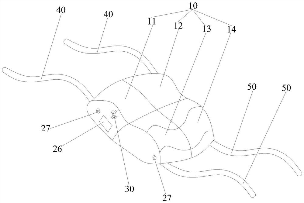
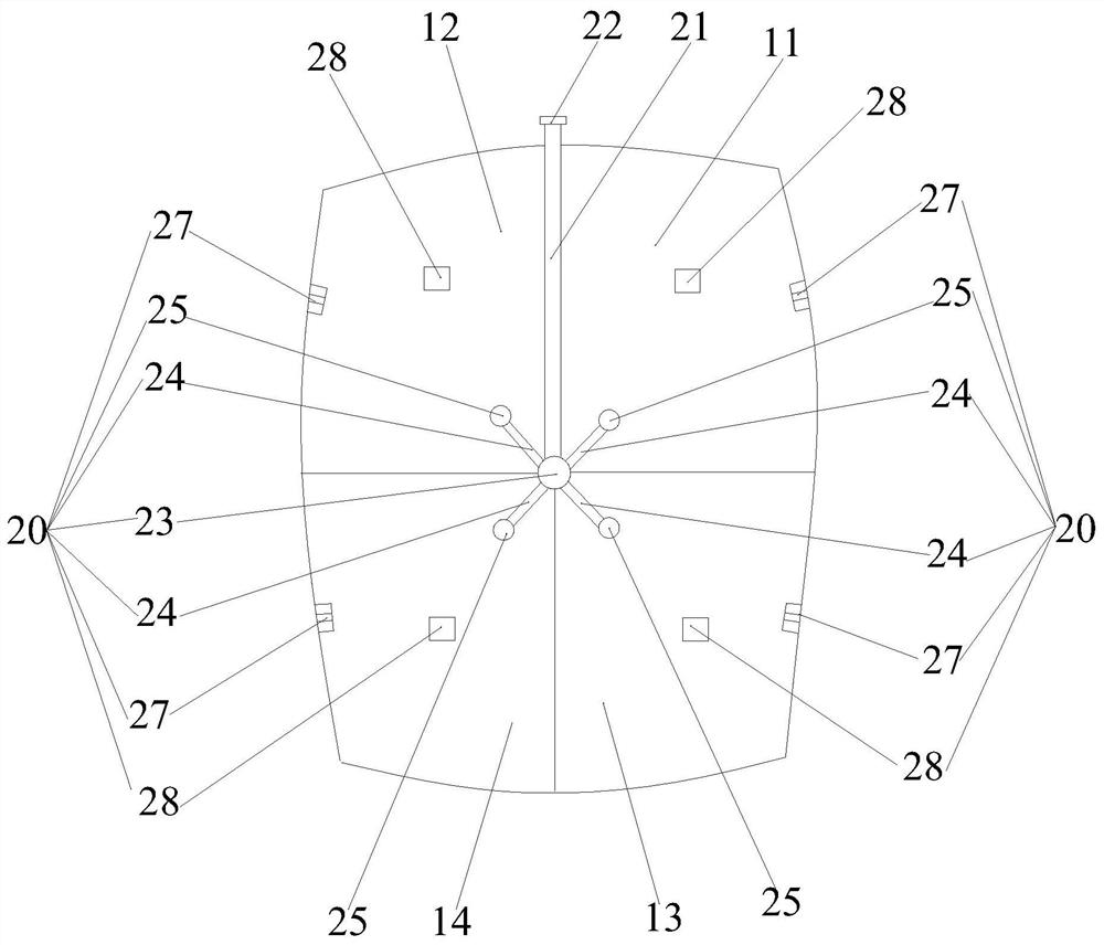
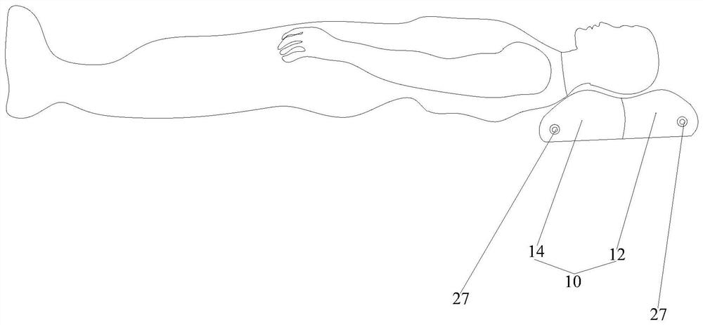

Embodiment Construction

[0026] It should be noted that, in the case of no conflict, the embodiments in the present application and the features in the embodiments can be combined with each other. The present invention will be described in detail below with reference to the accompanying drawings and examples.

[0027] According to the fixed headrest structure of the embodiment of the present invention, such as Figure 1 to Figure 3 As shown, the main airbag 10 and the air pressure regulating part 20 are included. The first diaphragm and the second diaphragm intersecting each other are arranged in the main airbag 10 to separate the main airbag 10 into a first airbag 11, a second airbag 12 and a third airbag 13. And the fourth air bag 14, the first air bag 11 and the second air bag 12 form the first supporting area, the third air bag 13 and the fourth air bag 14 form the second supporting area; the first air bag 11 and the third air bag 13 form the third supporting area , the second airbag 12 and the f...


PUM


Abstract

The invention provides a fixed head pillow structure. The fixed head pillow structure comprises a main air sac and an air pressure regulation component, wherein a first air sac, a second air sac, a third air sac and a fourth air sac are arranged in the main air sac; a first supporting region is formed by the first air sac and the second air sac, a second supporting region is formed by the third air sac and the fourth air sac, a third supporting region is formed by the first air sac and the third air sac, and a fourth supporting region is formed by the second air sac and the fourth air sac; andthe air pressure regulation component is used for regulating the air pressure in the first air sac, the second air sac, the third air sac and the fourth air sac to regulate the relative height of thefirst supporting region and the second supporting region as well as the relative height of the third supporting region and the fourth supporting region, so that a patient is at a horizontal position,and when the head is pillowed on the main air sac, the pitch angle and the bilateral deflection angle of the head of the patient are regulated; and therefore, according to the relationship between the healthy side and the diseased side of the patient, the head of the patient is regulated to an appropriate angle, so that the situation that the skin flap is dragged is avoided, and the blood supplyof the patient is guaranteed to be normal.

Description

technical field [0001] The invention relates to the field of medical rehabilitation appliances, in particular to a fixed headrest structure. Background technique [0002] Skin expansion is a common method for repairing facial and neck scars. The color, texture and elasticity of the skin flap in the thoracic triangle are similar to those of the face, so it has always been the focus of attention in plastic surgery. Using the pedicled flap after the expansion of the thoracic triangle to repair a large area of ​​facial and neck scars at one time, the clinical operation is simple, the postoperative appearance is improved, and the ideal repair effect can be achieved. [0003] After the operation is completed, the blood supply and survival of the flap play a decisive role in the success of the operation. After the flap is transferred, the flap pedicle is still located in the thoracic triangle. At this time, if the patient moves the head too much, the flap will be pulled, which wil...

Claims


Application Information

Patent Timeline
Patent Type & Authority Patents(China)
IPC IPC(8): A61G7/07A47G9/10G08B21/24
CPCA47G9/1027A61G7/072G08B21/24
Inventor 李梦凡胡大海王玲古兰石珊戴娇娇
Owner FOURTH MILITARY MEDICAL UNIVERSITY
Learn More