
Method and system for inspecting wafer defects

A wafer and defect technology, applied in the field of wafer inspection, can solve the problem that the wafer cannot accurately record the location of defects, etc., and achieve the effects of quick reference, high degree of visualization, and easy analysis

Active Publication Date: 2019-08-16
福建省福联集成电路有限公司
View PDF4 Cites 7 Cited by
  • Summary
  • Abstract
  • Description
  • Claims
  • Application Information

AI Technical Summary

Problems solved by technology

[0003] To this end, it is necessary to provide a method and system for inspecting wafer defects to solve the problem that existing wafer defects obtained through OM cannot accurately record the location of defects on the wafer

Method used


Image

  • Method and system for inspecting wafer defects
  • Method and system for inspecting wafer defects
  • Method and system for inspecting wafer defects

Examples


Embodiment Construction

[0041] In order to explain in detail the technical content, structural features, achieved goals and effects of the technical solution, the following will be described in detail in conjunction with specific embodiments and accompanying drawings.

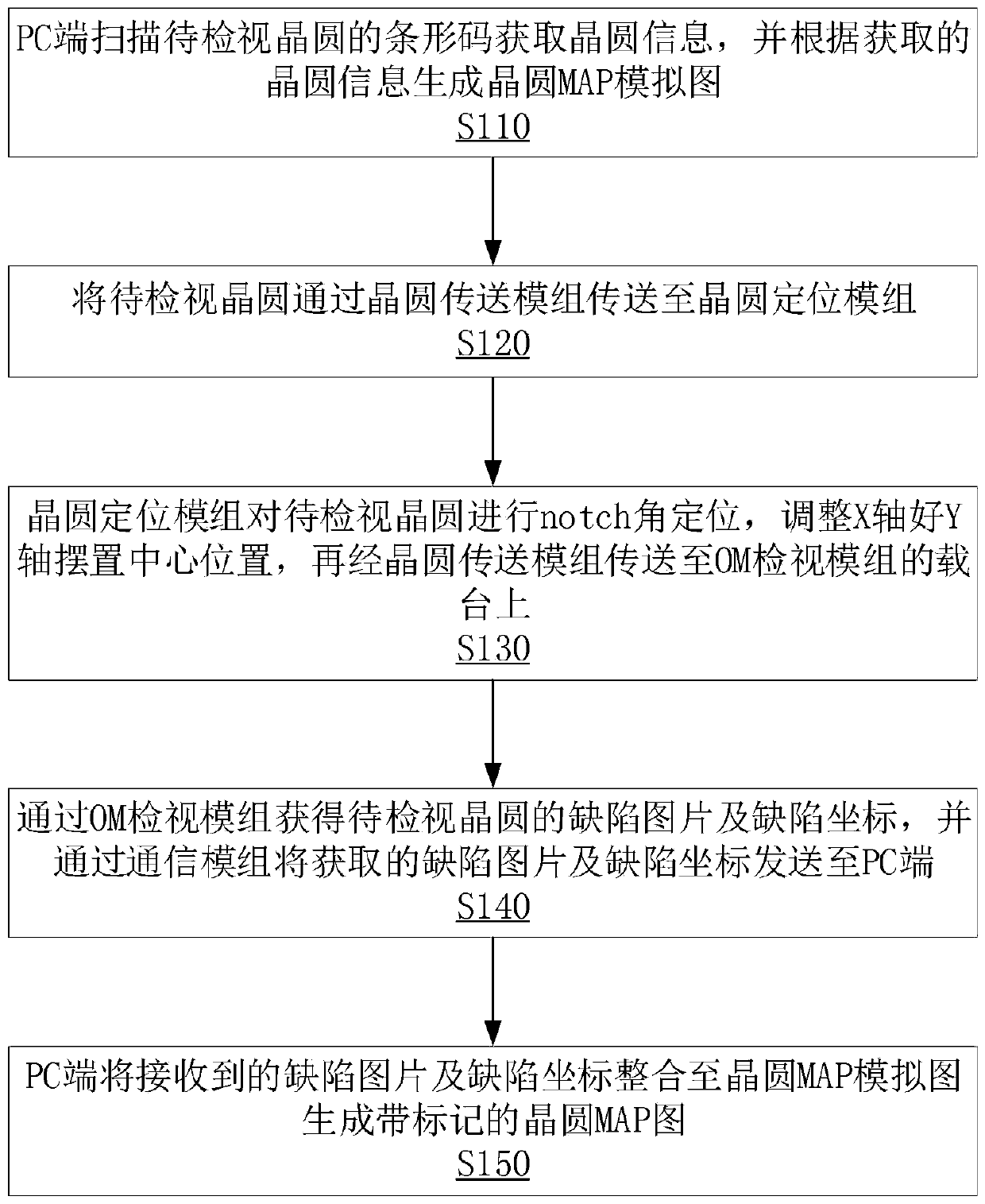
[0042] see figure 1 The method for inspecting wafer defects described in this embodiment includes the following steps:

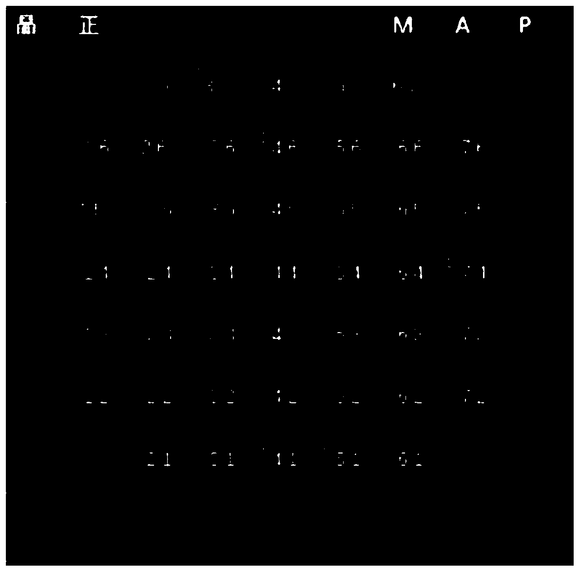
[0043] Step S110: The PC scans the barcode of the wafer to be inspected to obtain wafer information, and generates a simulation map of the wafer MAP according to the obtained wafer information; scans the barcode of the wafer to be inspected through the PC, identifies the wafer to be inspected and obtains the prior information. The entered wafer information, where the wafer information includes wafer size, shot size, PCM size, and dicing line size, etc., and generates a wafer MAP simulation diagram corresponding to the wafer to be inspected based on the obtained wafer information. Such as figure 2 and image 3 In...


PUM


Abstract

The invention relates to a method and system for inspecting wafer defects. The method comprises the steps that a PC scans the barcode of a wafer to be inspected to acquire wafer information, and generates a wafer MAP simulated diagram according to the acquired wafer information; a wafer conveying module conveys the wafer to be inspected to a wafer positioning module; the wafer positioning module performs notch angular positioning on the wafer to be inspected and adjusts the X-axis and Y-axis placement central positions, and the wafer conveying module conveys the wafer to be inspected to a carrier of an OM inspection module; the OM inspection module obtains the defect picture and the defect coordinates of the wafer to be inspected, and a communication module transmits the acquired defect picture and defect coordinates to the PC; the PC integrates the received defect picture and defect coordinates into the wafer MAP simulated diagram to generate a marked MAP of the wafer. The mark on themarked MAP of the wafer accurately indicates the location of defect on the wafer, facilitates analysis of defects in each layer of the wafer, provides a high degree of visualization, and can quicklyreview the defect pictures at the defect location.

Description

technical field [0001] The invention relates to the technical field of wafer inspection, in particular to a method and system for inspecting wafer defects. Background technique [0002] Wafers are the basic material for manufacturing semiconductor chips. When wafers are processed in different processes, it is necessary to inspect wafers for defects. In the existing inspection of the wafer, it is usually inspected by OM (Optical Microscopy, optical microscope). When a defect is found through inspection, the photo is taken and saved in a local file, which is not easy to find and inspect, and is easy to lose; and OM obtains The photos cannot accurately record the location of the defect on the wafer, and there are certain difficulties in the later traceability and analysis of the defect. Contents of the invention [0003] To this end, it is necessary to provide a method and system for inspecting wafer defects, so as to solve the problem that existing wafer defects obtained t...

Claims


Application Information

Patent Timeline
Patent Type & Authority Applications(China)
IPC IPC(8): H01L21/66G01N21/88G06T7/00
CPCH01L22/12H01L22/20G01N21/8851G06T7/0004G01N2021/888G01N2021/8864G06T2207/30148
Inventor 林锦伟郭文海翁佩雪赵玉会邓丹丹甘凯杰钟艾东林伟铭
Owner 福建省福联集成电路有限公司
Learn More