
Asymmetric furnace arch structure capable of reducing boiler flue gas temperature difference

A technology of flue gas temperature deviation and flame angle, which is applied to steam boiler components, steam boilers, steam boiler accessories, etc., and can solve the problems of increased deviation, steam temperature deviation, superheater, reheater tube wall overheating, etc. problem, to achieve the effects of reduced smoke temperature deviation, consistent heat transfer, and simple structure

Pending Publication Date: 2019-08-16
NORTHWEST BRANCH OF CHINA DATANG CORP SCI & TECH RES INST
View PDF0 Cites 0 Cited by
  • Summary
  • Abstract
  • Description
  • Claims
  • Application Information

AI Technical Summary

Problems solved by technology

[0003] However, the flue gas at the furnace outlet of the four-corner tangential circle boiler still has a strong residual rotation, and the guiding effect of the flame angle on the flue gas leads to the difference in the flue gas flow field and temperature distribution on the left and right sides of the flue. Average, there is a deviation in smoke temperature, and the degree of deviation will increase with the increase of unit capacity
The deviation of the flue gas temperature will lead to the deviation of the steam temperature on the left and right sides of the heating surface. In severe cases, it will cause the overheating of the tube wall of the superheater and reheater. Long-term operation will also lead to pipe bursts and other phenomena that seriously endanger the safe operation of the boiler.

Method used


Image

  • Asymmetric furnace arch structure capable of reducing boiler flue gas temperature difference
  • Asymmetric furnace arch structure capable of reducing boiler flue gas temperature difference
  • Asymmetric furnace arch structure capable of reducing boiler flue gas temperature difference

Examples


Embodiment Construction

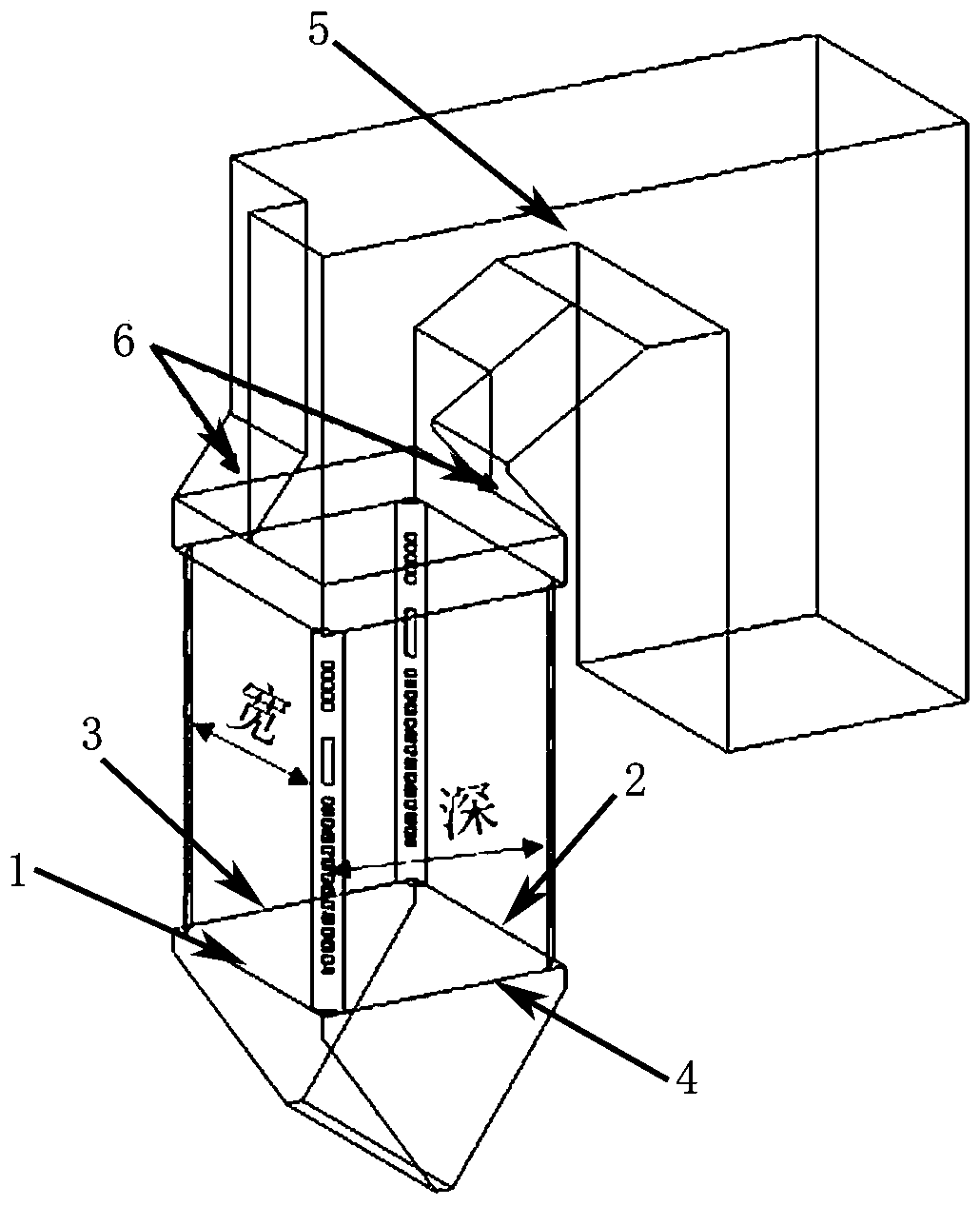
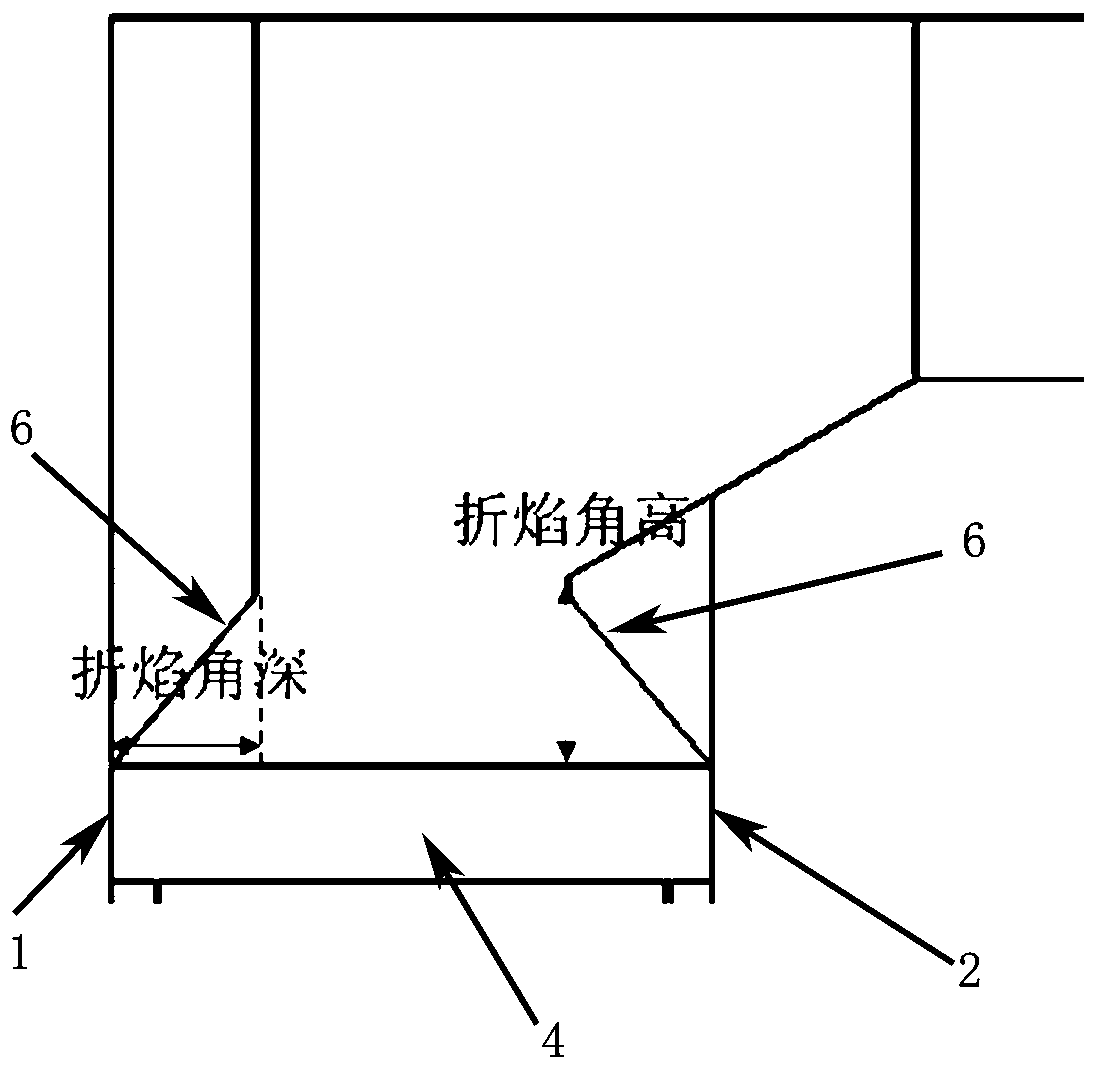
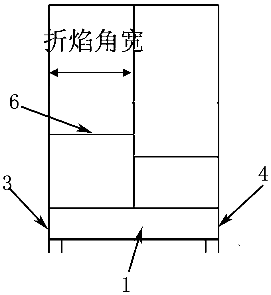
[0020] The present invention is an asymmetrical refraction angle 6 structure for reducing boiler flue temperature deviation, comprising a refraction angle 6 arranged at the junction of the horizontal flue 5 and the main combustion zone of the furnace, the main combustion zone of the furnace is defined by the front wall of the furnace 1. The back wall 2 of the furnace, the right wall 4 of the furnace and the left wall 3 of the furnace form a hollow columnar chamber; the said refraction angle 6 is set to two, and the two refraction angles 6 are respectively arranged on the front wall 1 of the furnace and the rear of the furnace On the wall 2; two refraction angles 6 are asymmetrically arranged on the front wall 1 and the rear wall 2 of the furnace.

[0021] The widths of the two refraction angles 6 are equal, and the width of the refraction angles 6 is half of the width of the furnace, which is the distance between the left wall 3 and the right wall 4 of the furnace.

[0022] Th...


PUM


Abstract

The invention discloses an asymmetric furnace arch structure capable of reducing boiler flue gas temperature difference, and relates to a structure of tangent arrangement of a combustor hearth, in particular to the asymmetric furnace arch structure capable of reducing the boiler flue gas temperature difference. The structure comprises two furnace arches which are arranged at the connecting position of a horizontal flue and a hearth main combustion area, and the two furnace arches are arranged on a hearth front wall and a hearth rear wall, and the two furnace arches are arranged on the hearth front wall and the hearth rear wall in an asymmetric manner. The structure is simple, when the main combustion area airflow rotates anticlockwises, the furnace arch, close to the left side, of the hearth front wall can guide the flow direction of the flue gas on the left side to the horizontal flue as far as possible, the deviation degree of the flue gas to the hearth front wall is greatly weakened, the guide effect on the flue gas on the right side is not changed, flue gas flow rates of the left side and the right side of a hearth outlet are finally consistent, and are consistent with the heatexchange amount of the heating face, and the flue gas temperature difference is greatly reduced.

Description

technical field [0001] The invention relates to a structure for tangentially arranging a burner furnace, in particular to an asymmetrical folded flame angle structure for reducing boiler smoke temperature deviation. Background technique [0002] Common types of boilers in coal-fired units in my country include four-corner tangential boilers, W flame boilers, and front and rear wall confrontation boilers. Among them, four-corner tangential boilers are the most widely used because of their advantages such as high flame fullness, sufficient combustion, and low pollutant emissions. . my country's four-corner tangential boilers mostly adopt a Π-type layout, that is, a panel superheater is arranged above the main combustion zone, a convection superheater and a reheater are arranged in a horizontal flue, and an economizer and a low-temperature superheater are arranged in a shaft flue. A refraction corner is arranged at the connection between the rear wall of the furnace wall and th...

Claims


Application Information

Patent Timeline
IPC IPC(8): F22B37/00F22G3/00
CPCF22B37/00F22G3/00
Inventor 赵斯楠
Owner NORTHWEST BRANCH OF CHINA DATANG CORP SCI & TECH RES INST
Learn More