
A hydraulic support cylinder structure

A technology of hydraulic support and support components, which is applied in the direction of support, fluid pressure actuating device, manufacturing tools, etc., can solve the problems that the gap between the processed parts cannot be tightly fitted, the accuracy and quality of the workpiece are reduced, and the cutting force of the workpiece is reduced. Achieve the effect of improving anti-pollution ability, reducing processing cost and reducing processing difficulty

Active Publication Date: 2020-04-07
江苏宏昌天马物流装备有限公司
View PDF19 Cites 0 Cited by
  • Summary
  • Abstract
  • Description
  • Claims
  • Application Information

AI Technical Summary

Problems solved by technology

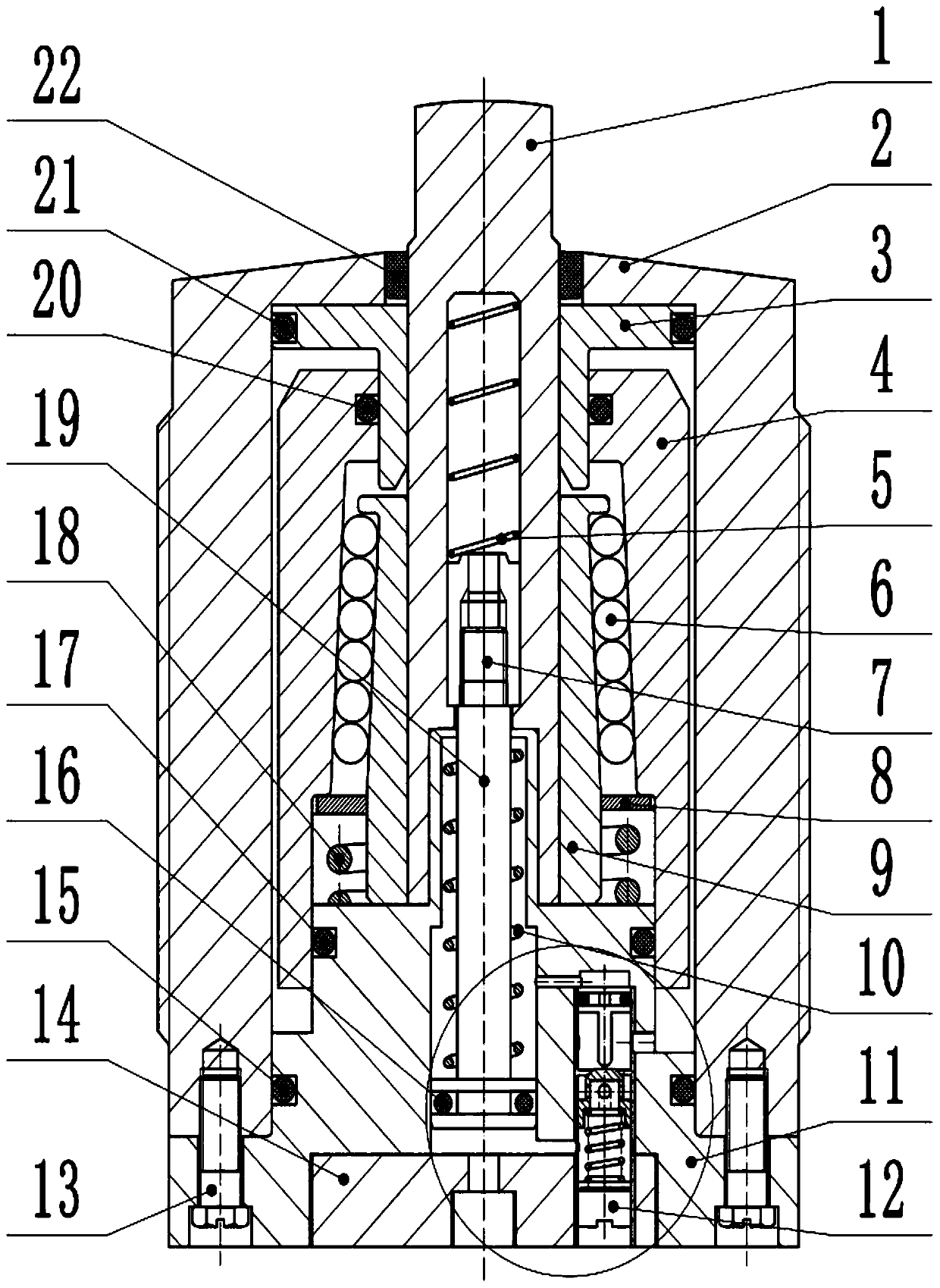
[0004] At present, the down-pressing action of the down-pressing piston of the hydraulic support cylinder on the market responds too quickly, and it will rebound when the supporting plunger touches the workpiece. The gap between the processed parts cannot be tightly fitted. In this case, the hydraulic support cylinder cannot play the role of reducing the cutting force received by the workpiece during processing, so the precision and quality of the processed workpiece will also be reduced.

Method used


Image

  • A hydraulic support cylinder structure
  • A hydraulic support cylinder structure
  • A hydraulic support cylinder structure

Examples


Embodiment Construction

[0027] The following will clearly and completely describe the technical solutions in the embodiments of the present invention with reference to the accompanying drawings in the embodiments of the present invention. Obviously, the described embodiments are only some, not all, embodiments of the present invention. Based on the embodiments of the present invention, all other embodiments obtained by persons of ordinary skill in the art without making creative efforts belong to the protection scope of the present invention.

[0028] The purpose of the present invention is to provide a hydraulic support cylinder structure to ensure that the support plunger fits the workpiece, provide a stable support force for the workpiece, reduce cutting vibration, and thereby improve the practicability and reliability of the hydraulic support cylinder.

[0029] In order to make the above objects, features and advantages of the present invention more comprehensible, the present invention will be fu...


PUM


Abstract

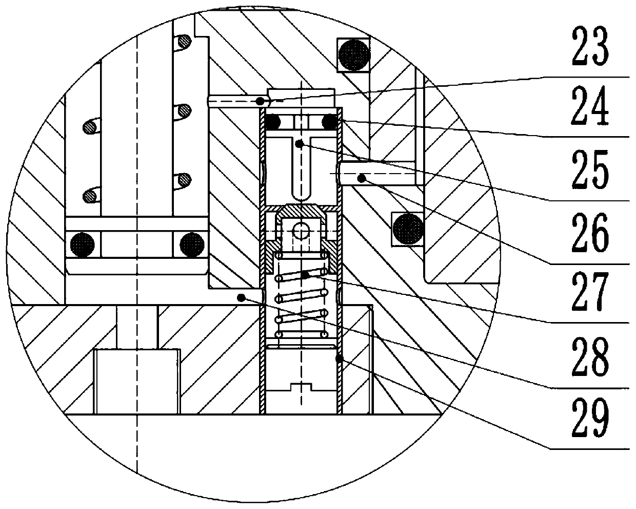
The invention discloses a hydraulic support cylinder structure, which completes the clamping action of the support cylinder in a sequential manner. After the piston rod rises to the position, the oil is connected to the hydraulic control rod and is pressed to open the one-way valve, and the oil reaches the down-pressing piston along the gap. On the upper side, press the piston down and move the support cylinder tightly. Compared with the prior art, the structure of the hydraulic support cylinder of the present invention can ensure that the hydraulic support cylinder can be held tightly after the support plunger fits the workpiece stably, so that the hydraulic support cylinder can provide stable support force and expand the pressing piston and cylinder The gap can enhance the anti-pollution ability of the hydraulic support cylinder and reduce the difficulty of processing and assembly.

Description

technical field [0001] The invention relates to the technical field of machine tool fixtures, in particular to a hydraulic support cylinder structure. Background technique [0002] The hydraulic support cylinder is one of the machine tool fixtures. It is a high-tech hydraulic component. Its main function is to support and fix the workpiece in a hydraulically driven manner. The hydraulic support cylinder can not only fix the workpiece to be processed, but also reduce the cutting vibration of the workpiece during processing, and prevent the workpiece from being deformed due to uneven force. This feature can greatly improve the precision and quality of the processed workpiece. [0003] The working process of the hydraulic support cylinder is divided into three steps: 1. Driven by the oil, the hydraulic support cylinder extends the internal piston rod and pushes the support plunger up to make the support plunger fit the workpiece stably; 2. Use its own The structure can hold th...

Claims


Application Information

Patent Timeline
Patent Type & Authority Patents(China)
IPC IPC(8): F15B15/14F15B15/20F16J15/16B23Q3/00
CPCF15B15/14F15B15/1423F15B15/1438F15B15/1447F15B15/1452F15B15/1471F15B15/149F15B15/202B23Q3/00F15B2215/30B23Q2703/04B23Q3/108
Inventor 翟富刚乔子石叶子王树胜杜鑫明张慧
Owner 江苏宏昌天马物流装备有限公司
Learn More