
Modular molding method of deflector

A deflector and metal tube technology, applied in the field of deflectors, can solve problems such as internal stress and deflector deformation, and achieve the effects of simplifying processing, realizing replacement, and solving compliance

Active Publication Date: 2020-05-08
湖北三江航天江北机械工程有限公司
View PDF6 Cites 0 Cited by
  • Summary
  • Abstract
  • Description
  • Claims
  • Application Information

AI Technical Summary

Problems solved by technology

[0004] The purpose of the present invention is to overcome the shortcomings of the above-mentioned background technology, and provide a modular forming method for the deflector, which solves the deformation caused by the welding and forming of the metal sheet used in the traditional processing method of the deflector through modular processing and forming and internal stress

Method used


Image

  • Modular molding method of deflector
  • Modular molding method of deflector
  • Modular molding method of deflector

Examples


Embodiment Construction

[0031] The implementation of the present invention will be described in detail below in conjunction with the examples of implementation, but they do not constitute a limitation of the present invention, and are only examples. At the same time, the advantages of the present invention will become clearer and easier to understand.

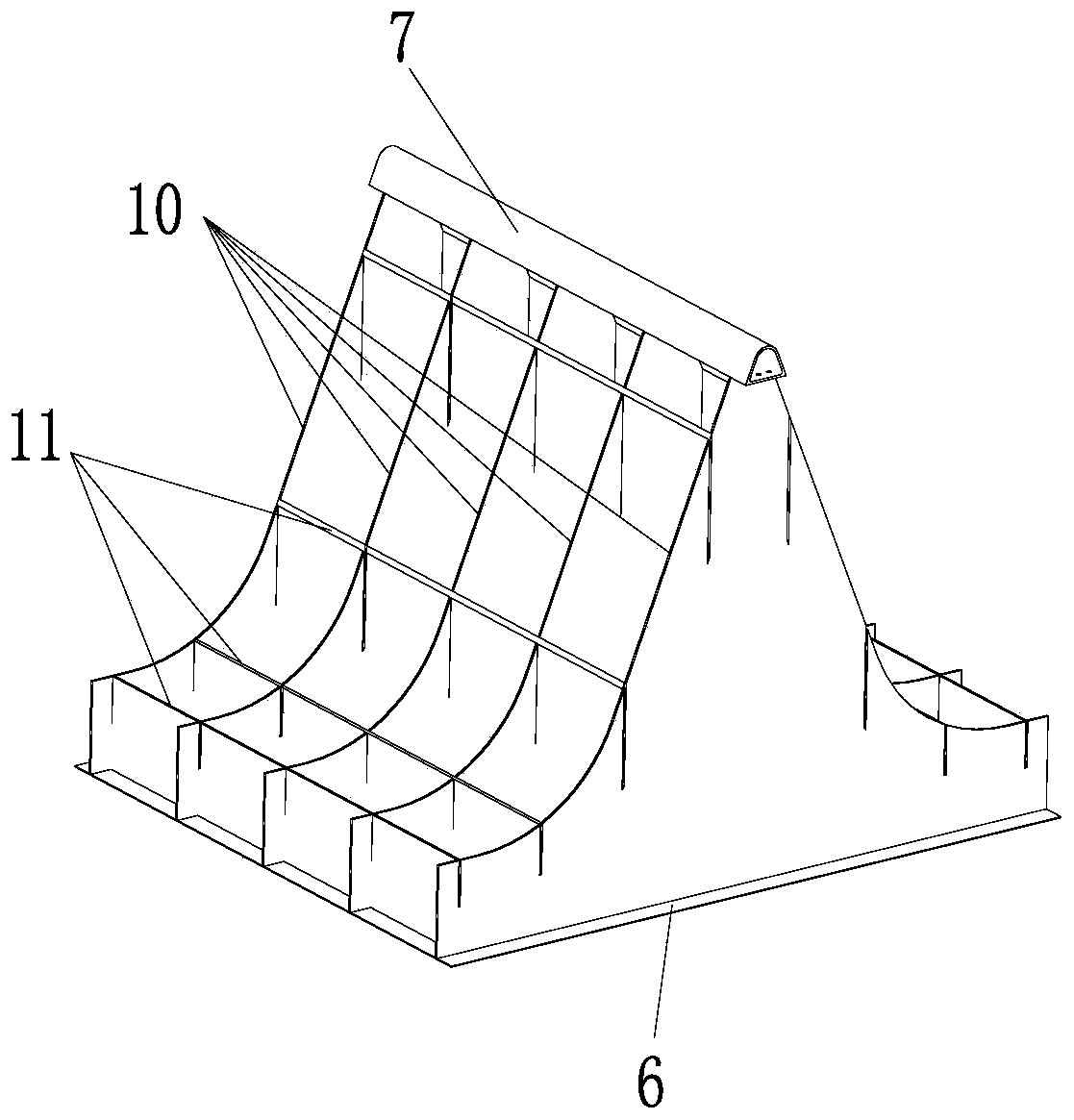
[0032] figure 1 Shown is a schematic structural view of the main part of the deflector welded by traditional thin plates. The composition and disadvantages of this structure have been described in the background art, and will not be repeated here.

[0033] A modular molding method for a deflector of the present invention comprises the following steps:

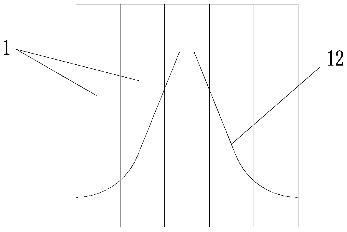
[0034] 1) Forming of the splicing module: according to the deflector (such as figure 2 shown), determine the cross-sectional shape and quantity of the appropriate metal pipe 1, the cross-sectional shape of the metal pipe 1 is polygonal or circular, and the outer sides of the metal pipe 1 are assembl...


PUM


Abstract

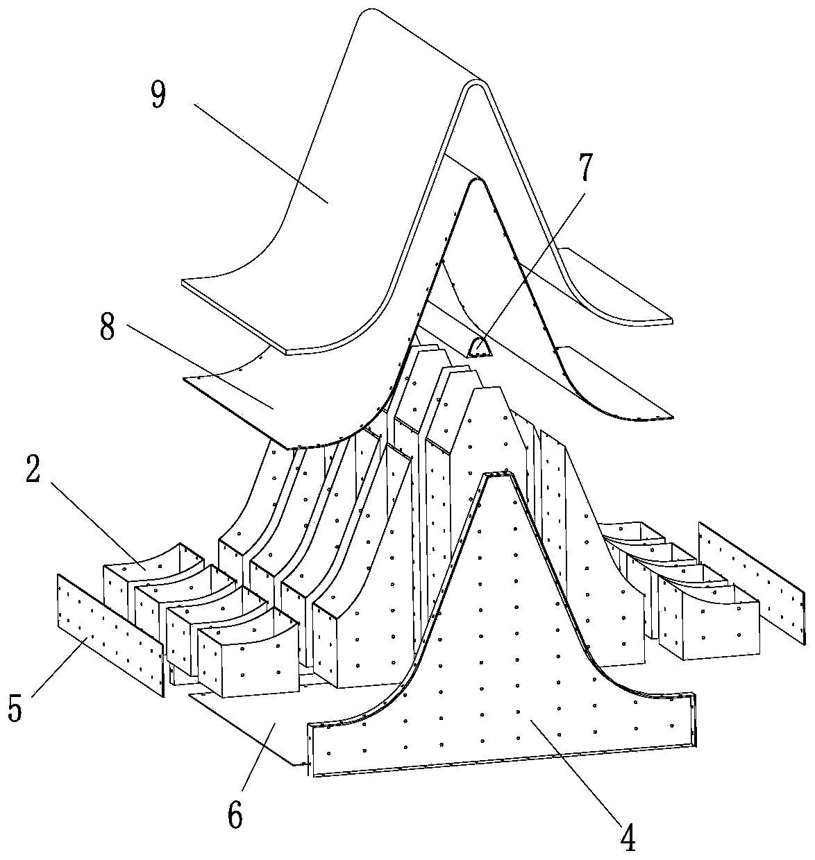
The invention discloses a modular forming method of a deflector. The method comprises the first step of forming of a splicing module, the second step of forming of an internal frame, the third step offorming of a peripheral structure, the fourth step of installation of a metal panel, and the fifth step of installation of a non-metal panel. A modularized metal pipe is adopted to construct the internal frame of the deflector for a rocket engine, the internal frame is connected with the metal panel, a bottom plate and a top cone part in a riveted or threaded more to form an integral structure through adapter connection of side plates on the periphery of the internal frame, and finally the non-metal panel and the metal panel are connected together through a bonding method. The problems of deformation and internal stress caused by welding and forming of a metal thin plate adopted in a traditional machining method of the deflector are solved.

Description

technical field [0001] The invention relates to the technical field of flow deflectors, in particular to a modular forming method for flow deflectors. Background technique [0002] When the rocket engine is ignited, it is necessary to use a deflector to guide the high-temperature and high-speed airflow ejected by the rocket engine in a certain direction, so as to prevent the uncontrolled airflow from scattering and impacting and causing damage to surrounding objects and the rocket itself. The main components of the deflector used in the rocket engine include the main part, the metal panel and the non-metallic panel (ablation-resistant layer), among which, the metal panel and the non-metallic panel must meet the specified shape to meet the diversion requirements. [0003] The traditional deflector manufacturing method is to combine the main part (such as figure 1 As shown, all spliced ​​metal sheets including longitudinal ribs 10, transverse ribs 11, bottom plate 6, and top ...

Claims


Application Information

Patent Timeline
Patent Type & Authority Patents(China)
IPC IPC(8): F02K9/95
CPCF02K9/95
Inventor 梁刚赖银燕张文任晗周萌
Owner 湖北三江航天江北机械工程有限公司
Learn More