Eureka AIR delivers breakthrough ideas for toughest innovation challenges, trusted by R&D personnel around the world.

Engine turbocharger overspeed diagnosis method and system, and vehicle

A technology of turbocharger and diagnosis method, applied in the direction of engine components, machines/engines, mechanical equipment, etc., can solve the problems of supercharger overspeed damage, calculation and diagnosis distortion, engine damage, etc., to reduce maintenance costs. Effect

Active Publication Date: 2019-08-16
SAIC GENERAL MOTORS +1
View PDF4 Cites 12 Cited by
  • Summary
  • Abstract
  • Description
  • Claims
  • Application Information

AI Technical Summary

Problems solved by technology

[0004] However, the above diagnostic method has problems such as insufficient reliability. In actual development or after-sales, supercharger overspeed failures often occur, and even cause the entire engine to be destroyed.
This is because neither the boost pressure nor the air flow is directly measured from the supercharger workload, and due to the complexity of the engine system, if there are abnormal conditions such as intake blockage or leakage of the booster line, it may cause booster damage. However, the supercharger speed calculated based on the boost pressure and air flow may still be within the normal range, which causes calculation and diagnosis distortion, which may lead to continuous failure of the supercharger due to misjudgment. Major problems such as overspeed damage or even destruction of the engine

Method used


Image

  • Engine turbocharger overspeed diagnosis method and system, and vehicle
  • Engine turbocharger overspeed diagnosis method and system, and vehicle
  • Engine turbocharger overspeed diagnosis method and system, and vehicle

Examples


Embodiment Construction

[0038] First of all, it should be noted that the specific steps, components, characteristics and advantages of the engine turbocharger overspeed diagnosis method, the engine turbocharger overspeed diagnosis system and the vehicle of the present invention will be specifically described below by way of example, but all The descriptions are for illustration only, and should not be construed as limiting the invention in any way.

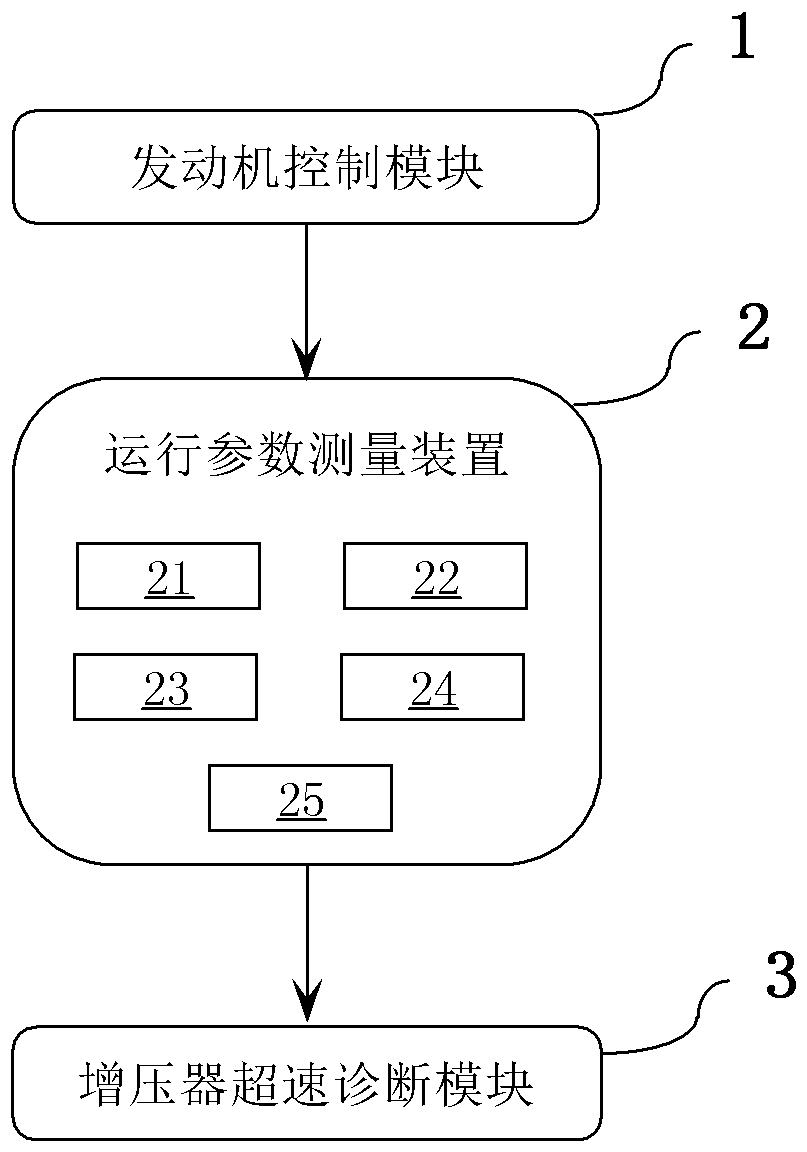
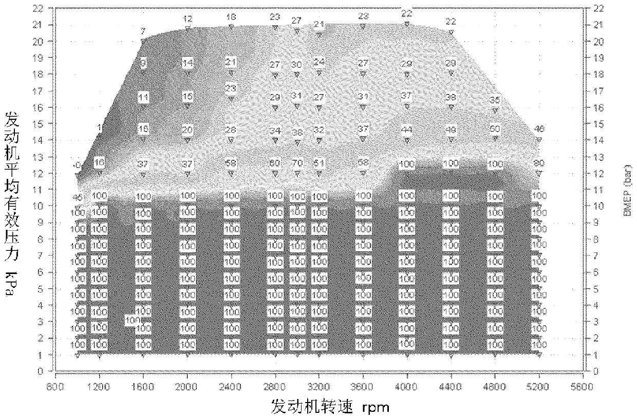
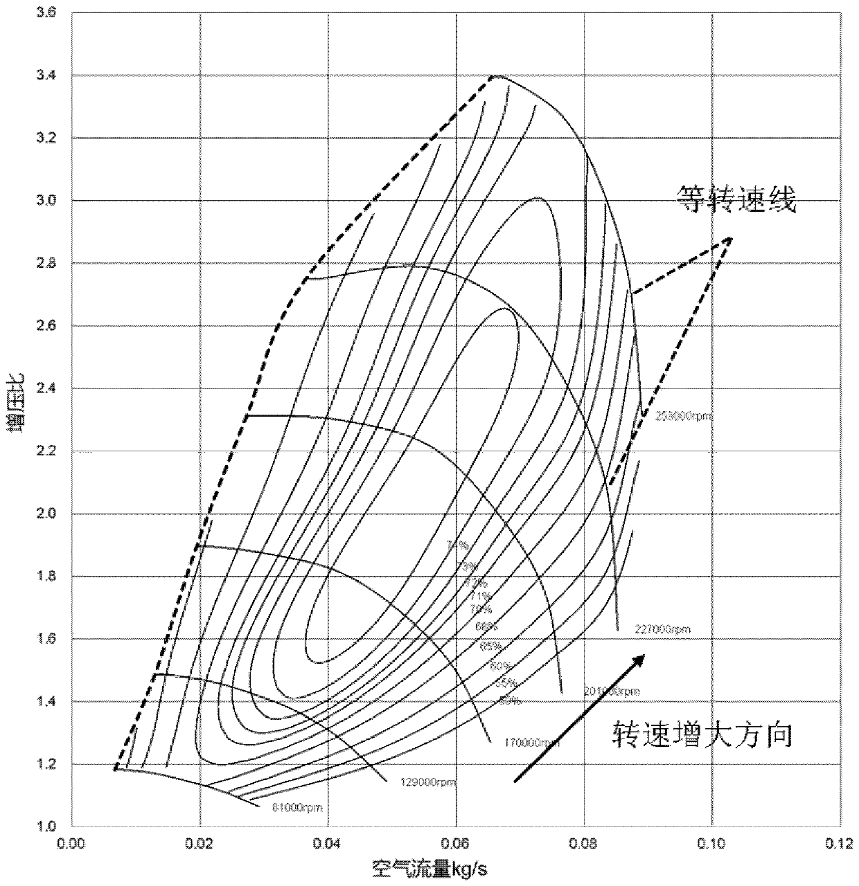
[0039] Please also see Figure 1 to Figure 3 , the flow of basic steps of a method for diagnosing an overspeed of an engine turbocharger according to the present invention is roughly shown through these drawings, which will be described in detail below.

[0040] In the above embodiment, the engine turbocharger overspeed diagnosis method includes the following steps:

[0041] First of all, in this overspeed diagnosis method, two thresholds need to be set as the basis for judging whether the engine turbocharger overspeed occurs, that is, the maximum speed...


PUM


Abstract

The invention relates to an engine turbocharger overspeed diagnosis method and system, and a vehicle. The engine turbocharger overspeed diagnosis method comprises the steps that a first threshold anda second threshold are set; operation parameters of an engine are obtained; obtained boost pressure and the obtained engine air flow are corrected into the boost pressure ratio and the air compressorflow under the standard atmosphere pressure and temperature condition correspondingly, then according to the corrected boost pressure ratio and the corrected air compressor flow, a performance pulse spectrogram of an air compressor of a turbocharger is inquired to obtain the predicted rotating speed of the turbocharger; according to the rotating speed of an engine and the opening degree of a throttle valve, a position pulse spectrogram of an air release valve actuator of the turbocharger is inquired to obtain the predicted opening degree of an air release valve, and the different value betweenthe predicted opening degree and the obtained opening degree of the air release valve of the turbocharger is calculated; and if the predicted rotating speed exceeds the first threshold, or the difference value exceeds the second threshold, it is judged that the turbocharger is subjected to overspeed, and if the predicted rotating speed does not exceeds the first threshold and the difference valuedoes not exceed the second threshold, it is judged that the turbocharger is not subjected to overspeed.

Description

technical field [0001] The invention relates to the technical field of automobiles, in particular to an engine turbocharger overspeed diagnosis method, an engine turbocharger overspeed diagnosis system and a vehicle. Background technique [0002] At present, on gasoline engines used in vehicles, turbocharging technology has become one of the important technical means to meet future fuel consumption regulations. The turbocharger is the core component of the supercharged engine. It often works under the condition of high temperature, high load and high speed. Or supercharger overspeed, supercharger overspeed is very harmful, not only will cause supercharger impeller shaft damage failure, and when the situation is serious, debris and oil will enter the cylinder and destroy the entire engine. [0003] Although there are mature turbocharger speed measurement equipment, there is a problem of high cost. At present, it is used in the engine development stage, and the turbocharger ...

Claims


Application Information

Patent Timeline
Patent Type & Authority Applications(China)
IPC IPC(8): F02B39/16F01D21/00
CPCF01D21/003F02B39/16F02B2039/168
Inventor 邓大伟郑有能黄伟达黄秋露刘杰
Owner SAIC GENERAL MOTORS
Why Eureka
Eureka Blog
Learn More