
Construction method of single pile vertical anti-pull static load test device

A technology of static load test and construction method, which is applied in the direction of foundation structure test, foundation structure engineering, construction, etc., and can solve the problems of many piled concrete blocks, high piled height, hidden safety hazards, etc.

Inactive Publication Date: 2019-08-16
中冶检测认证四川有限公司 +1
View PDF2 Cites 3 Cited by
  • Summary
  • Abstract
  • Description
  • Claims
  • Application Information

AI Technical Summary

Problems solved by technology

The existing static load test methods for foundation piles mainly include single surcharge method, single anti-anchor method and self-balancing method. In the static load test of large-tonnage foundation piles, the single surcharge method requires more concrete blocks , the height of the stacked load is high, so that the center of gravity of the stacked load moves upwards. During the test, a little carelessness will cause the stacked load to collapse, forming a serious safety hazard
The self-balancing method is a new type of static load test method for foundation piles. Its principle is to use the weight of the foundation pile itself and the frictional resistance of the soil around the pile above the neutral point of the pile to provide the load. The piles are poured together with the foundation piles. This method does not require a large amount of surcharge, nor does it require reaction piles, but the hydraulic loading system is for one-time use. After the test is completed, the parts of the hydraulic loading system must be grouted twice , the cost is high and the installation is cumbersome. It is suitable for the situation where the soil around the pile is good and can provide sufficient frictional resistance, so the scope of application is limited

Method used


Image

  • Construction method of single pile vertical anti-pull static load test device
  • Construction method of single pile vertical anti-pull static load test device
  • Construction method of single pile vertical anti-pull static load test device

Examples


Embodiment 1

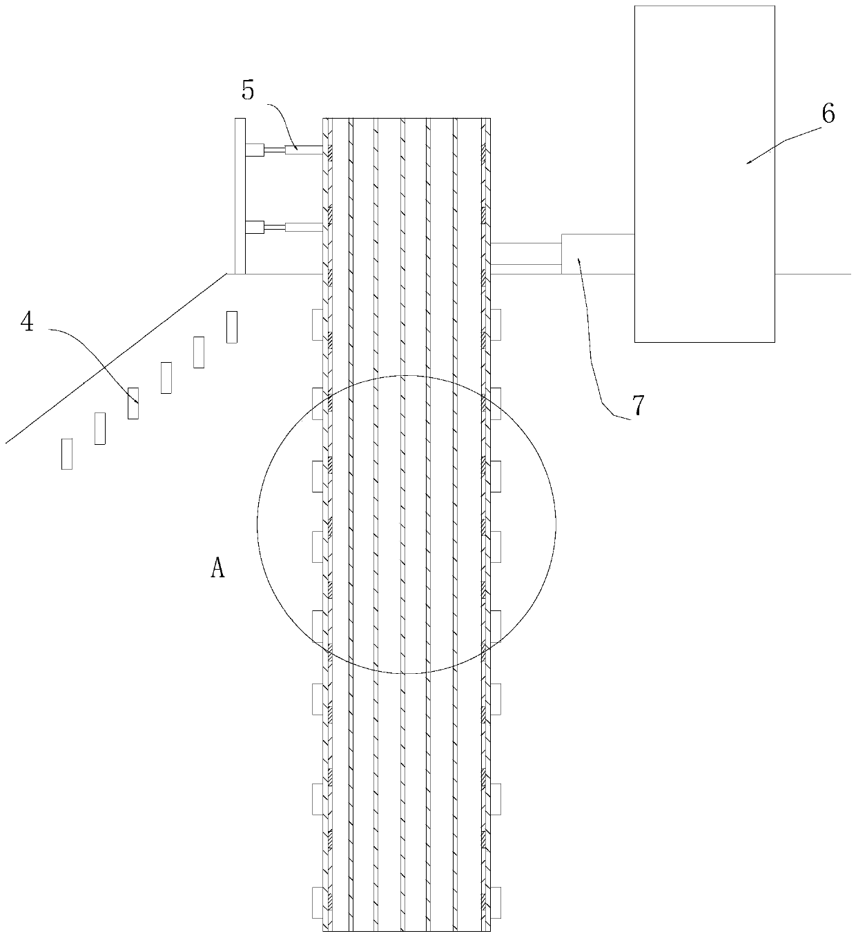
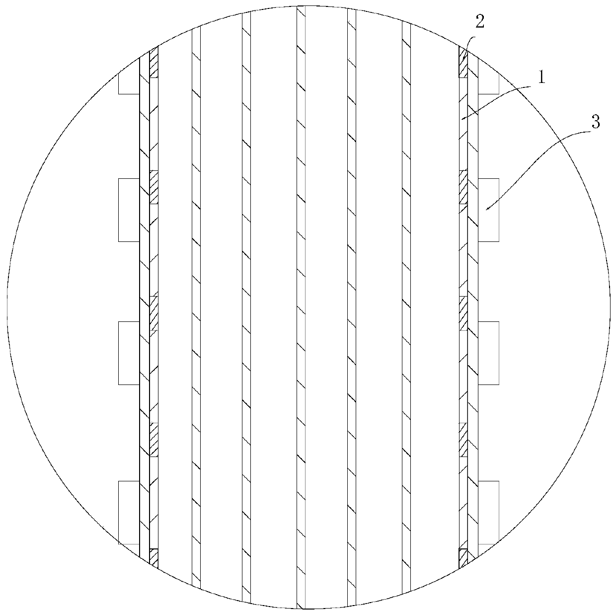
[0029] see Figure 1 to Figure 3 , when the output end of the jack 7 in the present invention applies pressure to the pile under inspection, the digital display displacement meter 6 arranged on the top of the pile under inspection performs data observation on the displacement of the pile top of the pile under pressure, and sets The inclinometer tube 1 on the steel cage of the pile under inspection conducts data observation on the displacement of the pile body under compression, and the reinforcement meter 2 installed on the reinforcement cage of the pile under inspection performs data observation on the pile body of the pile under inspection. Data observation is performed on the displacement that occurs under pressure, and the pile side soil pressure box 3 and the pile front side soil pressure box 4 arranged outside the pile body of the pile under inspection are used to observe the pressure data of the soil outside the pile body of the pile under inspection.

[0030] A constru...

Embodiment 2

[0041] The construction method of the single pile vertical pull-out static load test equipment of this embodiment is basically the same as that of Embodiment 1, the difference is that the termination loading conditions in step (S6) include breaking of the pile body, horizontal displacement of the pile body exceeding 100mm, load-displacement (H~Y0) curves show obvious bending tendency, the horizontal displacement of the pile body increases sharply under constant load, the displacement rate gradually accelerates, the reaction force structure is damaged or the horizontal loading device reaches the limit, and the test cannot be continued. In the present invention, when the test is carried out until the above-mentioned termination loading condition is met, the load is unloaded in stages to zero, thereby avoiding the deviation of test results and improving the accuracy of the test.

Embodiment 3

[0043] The construction method of the single pile vertical pull-out static load test equipment of the present embodiment is basically the same as that of embodiment 1, the difference is that in the step (S6), according to the estimated horizontal limit load of the single pile, it is divided into 10 grades, wherein the first grade The load is zero, so the level 1 and level 2 loads are combined into level 1, and the field test is carried out according to level 9. For each level of loading, the settlement of the bearing plate is read and recorded once every 5, 10, 15 and 30 minutes, and every half hour thereafter; when the settlement within one hour after each level of loading is less than 0.1mm, it is considered to have reached the relative Stable, the next level of load can be added.


PUM


Abstract

The invention discloses a construction method of a single pile vertical anti-pull static load test device, and belongs to the field of construction inspection. The construction method of the single pile vertical anti-pull static load test device sequentially comprises the following steps that inclinometer casings are tied symmetrically to the curved neutral surface, located on a pile body, of a to-be-tested pile reinforcement cage; reinforcement meter are symmetrically arranged on the tensioned and pressed main reinforcements away from the neutral axis; pile side soil pressure boxes are symmetrically arranged on the two pairs of force surfaces of the to-be-tested pile, and pile front side soil pressure boxes are distributed in the surface slope direction of the to-be-tested pile; digital readout displacement meters are mounted on the two sides and the middle part of the force surfaces of the to-be-tested pile, and at the same time the digital readout displacement meters are mounted above the force surfaces of the to-be-tested pile; a reaction wall is preset on one side of the to-be-tested pile, and a jack is mounted between the reaction wall and the to-be-tested pile; and a low speed load maintenance method is adopted. According to the construction method of the single pile vertical anti-pull static load test device, the potentials of a foundation and a rock and soil body is fully exerted, or safety of engineering design is improved, and the high efficiency of the foundation of a electric transmission line iron tower foundation is realized.

Description

technical field [0001] The invention relates to the field of construction detection, in particular to a construction method of single pile vertical uplift static load test equipment. Background technique [0002] Pile static load test is a kind of geotechnical engineering in-situ test method. It is a common test method used to test whether engineering piles can meet the design requirements. It is also required by JGJ94 "Technical Specifications for Building Pile Foundations". A test method. The existing static load test methods for foundation piles mainly include single surcharge method, single anti-anchor method and self-balancing method. In the static load test of large-tonnage foundation piles, the single surcharge method requires more concrete blocks , the height of the stacked load is high, so that the center of gravity of the stacked load moves upwards. During the test, a little carelessness will cause the stacked load to collapse, forming a serious safety hazard. Th...

Claims


Application Information

Patent Timeline
Patent Type & Authority Applications(China)
IPC IPC(8): E02D33/00
CPCE02D33/00
Inventor 刘进波马德翠李耀家巫燕彭波
Owner 中冶检测认证四川有限公司
Learn More