Forming technique using springs to adjust mobile cavity

A technology of movable cavity and molding process, applied in the direction of coating, etc., can solve the problems of uneven thickness, large flow resistance, and difficult to form, and achieve the effect of not easy to separate from each other, uniform thickness, and easy to form.

Inactive Publication Date: 2019-08-16
KAIPING YINGGUANG ELECTROMECHANICAL TECH
View PDF1 Cites 0 Cited by
  • Summary
  • Abstract
  • Description
  • Claims
  • Application Information

AI Technical Summary

Problems solved by technology

[0003] However, in the existing injection molding, the materials used for injection molding must have good fluidity in order to fill the cavity to obtain products.
[0004] For materials used for injection molding with poor fluidity, the existing plastic processing method of injection molding is used. During the molding process, due to the poor fluidity of the material, the flow resistance is large and it is not easy to form. In order to achieve product molding, it must be increased. Injection pressure and increased injection speed, increasing injection pressure and increasing injection speed will lead to large internal stress of the molded product, poor appearance, uneven thickness, and easy separation of composite materials, resulting in poor product quality and low yield
[0005] In the process of forming thin-walled products, even if injection molding materials with good fluidity are used, the flow resistance of liquid raw materials is large due to the small cavity, which makes it difficult to form. In order to achieve product molding, the injection pressure must be increased and the injection speed must be increased. Injection pressure and increased injection speed will lead to large internal stress of the molded product, poor appearance, uneven thickness, and easy separation of composite materials, resulting in poor product quality and low yield

Method used


Image

  • Forming technique using springs to adjust mobile cavity
  • Forming technique using springs to adjust mobile cavity
  • Forming technique using springs to adjust mobile cavity

Examples


Embodiment Construction

[0040] The molding process of adjusting the movable cavity through the spring in the present invention is suitable for producing thin-walled products, battery back covers, mobile phone cases or optical products, and the materials used are high-viscosity materials or low-viscosity materials, composite materials that are not Composite materials separated from each other.

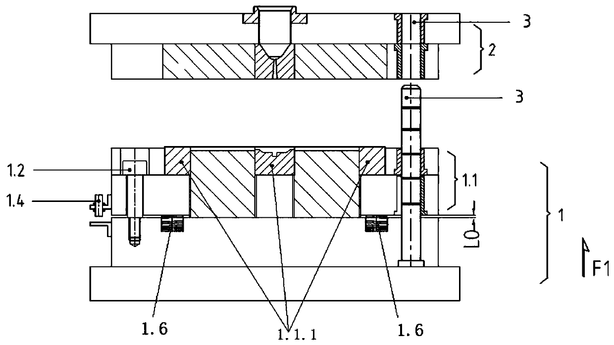
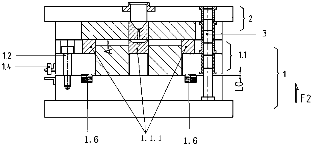
[0041] refer to figure 1 , figure 2 , image 3 , Figure 4 , Figure 5 , Image 6 , Figure 7 , Figure 8 , Figure 9 , Figure 10 , Figure 11 , Figure 12 , Figure 13 and Figure 14 , to describe in detail the preferred embodiments 1 and 2 of the molding process of adjusting the movable cavity through the spring of the present invention.

[0042] In the first preferred embodiment of the present invention, it is a molding process of a thin-walled product such as a light guide plate.

[0043] The thickness of the light guide plate is 0.4mm, the length is 152mm, and the width is 70mm. The raw mate...


PUM

PropertyMeasurementUnit
thicknessaaaaaaaaaa

Abstract

The invention provides a forming technique using springs to adjust a mobile cavity. The forming technique is characterized by comprising the following steps that when a second movable mechanism makescontact with a fixed mould, a mobile cavity A is formed by a movable mould, the fixed mould and the second movable mechanism, die assembly is conducted, then a mobile cavity D is formed, the volume ofthe mobile cavity is adjusted so that a mobile cavity B can be formed, a liquid material is injected into the mobile cavity B, the mobile cavity is moved, the volume of the mobile cavity is graduallydecreased to the required volume of a product, and a mobile cavity E is formed, and the product is cooled and formed. According to the forming technique using the springs to adjust the mobile cavity,the size of the mobile cavity can be adjusted according to requirements of the product due to the mobile cavity, then the volume of the mobile cavity before compression is stopped is larger than thevolume of the product, the liquid material can flow easily in the large-volume mobile cavity, the product can be formed easily, in addition, the internal stress of the product is good, the appearanceis attractive, the thickness is even, and composite materials cannot be separated easily.

Description

technical field [0001] The invention relates to a forming process, in particular to a forming process for adjusting a movable cavity through a spring. Background technique [0002] The existing plastic processing method of injection molding is that after the plastic is plasticized in the heating barrel of the injection molding machine, it is injected into the cavity of the closed mold by a plunger or a reciprocating screw to form a plastic processing method of the product. This method can process complex shapes and sizes. Products with precision or inserts have high production efficiency, and most thermoplastics and some thermosetting plastics (such as phenolic plastics) can be processed by this method. [0003] However, the materials used for injection molding in the existing injection molding must have good fluidity in order to fill the mold cavity to obtain products. [0004] For materials used for injection molding with poor fluidity, using the existing plastic processi...

Claims


Application Information

Patent Timeline
Patent Type & Authority Applications(China)
IPC IPC(8): B29C45/00B29C45/03B29C45/26B29C45/36B29C45/80B29C45/77
CPCB29C45/0055B29C45/03B29C45/26B29C45/2602B29C45/36B29C45/77B29C45/80B29C2045/2697
Inventor 徐雄石茂东吴世海
Owner KAIPING YINGGUANG ELECTROMECHANICAL TECH
Why Eureka
Try Eureka