Electronic endoscope for medical imaging

An electronic endoscope, medical imaging technology, applied in endoscopy, medical science, application and other directions, can solve the problems of increasing the pain and discomfort of patients, poor imaging resolution, diffuse reflection of light, etc., and achieve diagnostic efficiency. High, improved clarity, reduced pain and discomfort

Inactive Publication Date: 2019-08-16
牛欣青
View PDF10 Cites 0 Cited by
  • Summary
  • Abstract
  • Description
  • Claims
  • Application Information

AI Technical Summary

Problems solved by technology

[0005] The invention provides an electronic endoscope for medical image imaging, which has the advantages of strong light capture ability, clear imaging, high diagnosis efficiency, and reduces the pain and discomfort of patients during diagnosis, and solves the problem of existing problems. When the electronic endoscope uses the lighting lens to irradiate the human organs, because the surface of the organs is relatively rough, the diffuse reflection of the light is more serious, and a lot of light is exhausted in the process of diffuse reflection, which cannot be detected The objective lens captures less light information, which eventually leads to poor imaging clarity of the CCD and cannot meet the doctor's diagnostic needs. It is necessary to use the endoscope to enter the human body for observation many times, which is relatively inefficient. Problems that increase pain and discomfort for patients at the time of diagnosis

Method used


Image

  • Electronic endoscope for medical imaging
  • Electronic endoscope for medical imaging
  • Electronic endoscope for medical imaging

Examples


Embodiment Construction

[0023] The following will clearly and completely describe the technical solutions in the embodiments of the present invention with reference to the accompanying drawings in the embodiments of the present invention. Obviously, the described embodiments are only some, not all, embodiments of the present invention. Based on the embodiments of the present invention, all other embodiments obtained by persons of ordinary skill in the art without making creative efforts belong to the protection scope of the present invention.

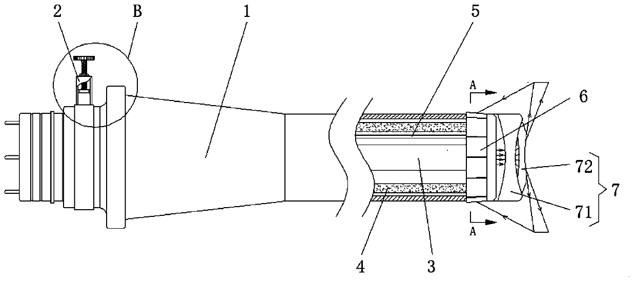
[0024] see figure 1 , an electronic endoscope for medical imaging, comprising a coiled tube channel 1, a negative pressure mechanism 2 is fixedly installed on the top of one side of the coiled tube channel 1, an illuminating optical fiber 3 is fixedly installed in the middle of the inner cavity of the coiled tube channel 1, and the side of the coiled tube channel 1 A CCD video line 4 is provided between the inner wall and the outer surface of the lighting fibe...


PUM


Abstract

The invention relates to the technical field of medical imaging equipment, and discloses an electronic endoscope for medical imaging. The electronic endoscope comprises a coil pipe channel; a negativepressure mechanism is fixedly installed on the top of one side of the coil pipe channel; a lighting optical fiber is fixedly installed in the middle of an inner cavity of the coil pipe channel; charge coupled device (CCD) video lines are arranged between the inner wall of the coil pipe channel and the outer surface of the lighting optical fiber; an airflow pipeline is arranged between the lighting optical fiber and the CCD video line and is positioned on the top of the inner cavity of the coil pipe channel; an objective lens is fixedly installed at the right side of the exterior of the coil pipe channel; a lighting lens is fixedly installed at one side of the objective lens. The electronic endoscope for medical imaging is provided with the negative pressure mechanism and the objective lens, and the angle of the objective lens can be adjusted by means of the negative pressure mechanism, so that the ability to capture light is improved, and more light information can be further transmitted to a CCD; compared with the existing endoscope, the electronic endoscope provided by the invention effectively increases the captured light information, so that the sharpness of imaging of the electronic endoscope is improved.

Description

technical field [0001] The invention relates to the technical field of medical imaging equipment, in particular to an electronic endoscope for medical imaging. Background technique [0002] Electronic endoscope is a medical electronic optical instrument that can be directly inserted into the body cavity or organ cavity for diagnosis. It uses extremely small electronic imaging components to transmit the observed image signals to the image processor, and then Image information is provided directly on the monitor for observation and diagnosis by doctors. [0003] However, when the existing electronic endoscope utilizes the lighting lens to irradiate the human organs, because the surface of the organs is relatively rough, the phenomenon of diffuse reflection of light is relatively serious, and a lot of light is exhausted in the process of diffuse reflection. Furthermore, it cannot be captured by the objective lens, so that it captures less light information, which eventually le...

Claims


Application Information

Patent Timeline
Patent Type & Authority Applications(China)
IPC IPC(8): A61B1/04A61B1/07
CPCA61B1/00163A61B1/042A61B1/07
Inventor 邹晓辉
Owner 牛欣青
Why Eureka
Try Eureka