Display components and mobile terminals
A display component and display module technology, applied in the direction of electrical components, antenna components, identification devices, etc., can solve the problems of fixed and limited antenna layout areas, increased mutual interference of antenna signals, etc., to ensure signal stability and accuracy, The effect of expanding the layout range and multi-antenna layout
- Summary
- Abstract
- Description
- Claims
- Application Information
AI Technical Summary
Problems solved by technology
Method used
Image
Examples
Embodiment 1
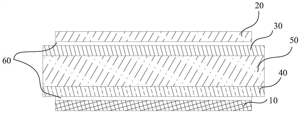
[0043] Such as Figure 1 to Figure 4 As shown, the display assembly provided by the embodiment of the present invention includes a display module 10 , a first transparent plate 20 , an antenna layer 30 , a ground layer 40 and a second transparent plate 50 .
[0044] The first transparent plate 20 is disposed on one side of the display module 10 . The antenna layer 30 is located between the display module 10 and the first transparent plate 20 for sending and receiving signals; the ground layer 40 is arranged between the display module 10 and the antenna layer 30, and the ground layer 40 is isolated from the antenna layer 30 The antenna layer 30 is disposed on the first surface of the second transparent plate 50, the ground layer 40 is disposed on the second surface of the second transparent plate 50, and the first surface is parallel to the second surface.
[0045]In this embodiment, the arrangement of the antenna layer 30 makes the plane where the entire display assembly is l...
Embodiment 2
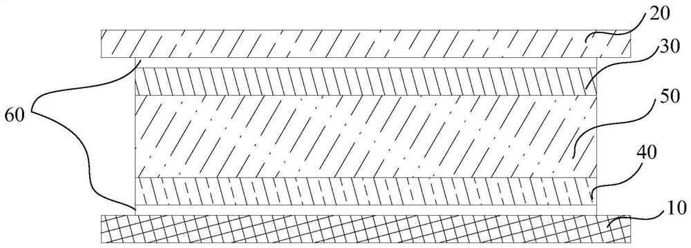
[0067] Embodiment 2 of the present invention relates to a display component. Embodiment 2 is substantially the same as Embodiment 1. The main difference is that: Figure 6 to Figure 9 As shown, the ground layer 40 is arranged on the surface of the second transparent plate 50; the antenna layer 30 is arranged on the surface of the first transparent plate 20; the antenna layer 30 and the ground layer 40 are located on the first transparent plate 20 and the second transparent plate 50 between.
[0068] In this embodiment, the ground layer 40 is disposed on the surface of the second transparent plate 50, and the antenna layer 30 is disposed on the surface of the first transparent plate 20, so the second transparent plate 50 can provide protection and support for the ground layer 40 , the first transparent plate 20 can provide protection and support for the antenna layer 30, thereby avoiding the damage of the antenna layer 30 and the ground layer 40 due to the damage of the transpa...
Embodiment 3
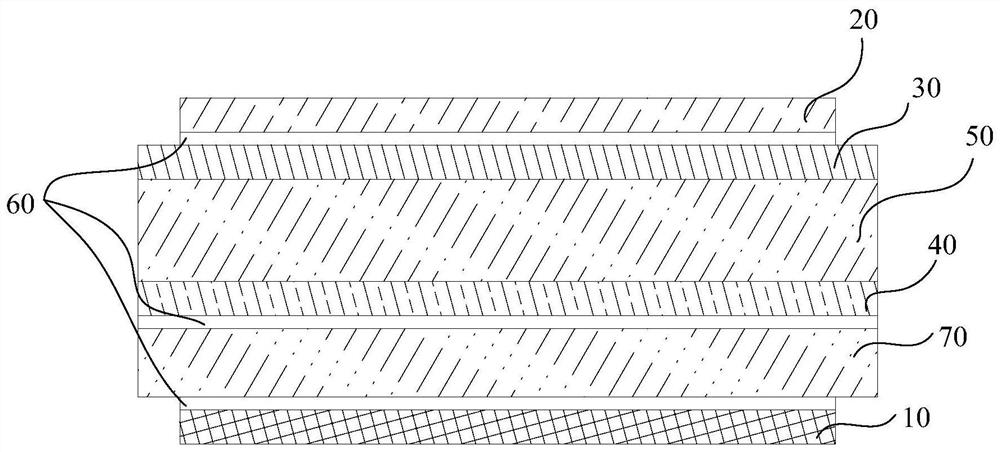
[0078] Embodiment 3 of the present invention relates to a display component. Embodiment 3 is substantially the same as Embodiment 1, and the main difference is that: Figure 11 to Figure 14 As shown, the ground layer 40 is disposed on the surface of the second transparent plate 50, and the ground layer 40 is located between the second transparent plate 50 and the display module 10; the antenna layer 30 is disposed on the surface of the first transparent plate 20, and the antenna layer 30 is located between the first transparent plate 20 and the second transparent plate 50 .
[0079] In this embodiment, the antenna layer 30 is arranged between the first transparent board 20 and the second transparent board 50, and the antenna layer 30 is arranged on the first transparent board 20, and the ground layer 40 is arranged between the display module 10 and the second transparent board 50. between the transparent plates 50, and the ground layer 40 is arranged on the second transparent ...
PUM
 Abstract
Description
Claims
Application Information
 - R&D
- Intellectual Property
- Life Sciences
- Materials
- Tech Scout
- Unparalleled Data Quality
- Higher Quality Content
- 60% Fewer Hallucinations
Browse by: Latest US Patents, China's latest patents, Technical Efficacy Thesaurus, Application Domain, Technology Topic, Popular Technical Reports.
© 2025 PatSnap. All rights reserved.Legal|Privacy policy|Modern Slavery Act Transparency Statement|Sitemap|About US| Contact US: help@patsnap.com


