
Coiled bar reinforcing steel bar rotating frame

A technology of rotating frame and steel bar is applied in the field of steel structure rotating support, which can solve the problems of affecting the speed of steel wire coiling, increase in production cost, low resource utilization rate, etc., so as to improve construction efficiency, low production cost, and turnover times many effects

Inactive Publication Date: 2019-08-13
MCC5 GROUP CORP SHANGHAI
View PDF6 Cites 2 Cited by
  • Summary
  • Abstract
  • Description
  • Claims
  • Application Information

AI Technical Summary

Problems solved by technology

The steel bar circle has a certain degree of elasticity, which is easy to cause injury to the workers next to it during the adjustment process, and also affects the speed of the steel bar circle. At the same time, the friction between the steel bar itself and the ground, iron frame, etc. will cause the steel wire itself to be damaged
This will not only waste labor, but also lower the utilization rate of existing resources, and the production cost will also increase accordingly.
[0003] Therefore there are above-mentioned inconveniences and problems in the known straightening arrangement mode of the round steel bar

Method used


Image

  • Coiled bar reinforcing steel bar rotating frame
  • Coiled bar reinforcing steel bar rotating frame
  • Coiled bar reinforcing steel bar rotating frame

Examples


Embodiment 1

[0025] The round steel bar rotating frame of the present invention includes a pre-embedded pipe and a rotating unit.

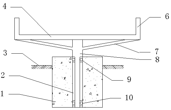
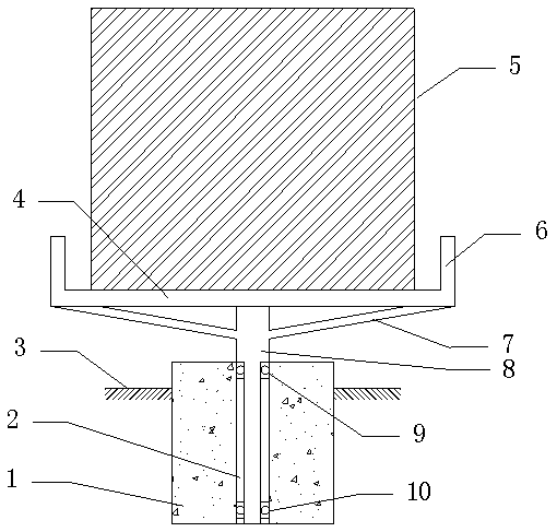
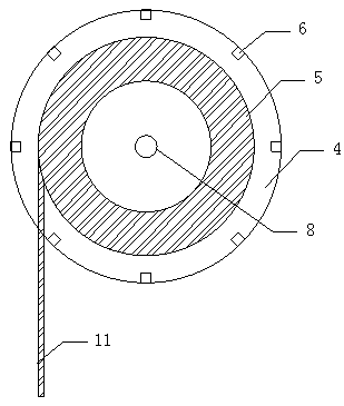
[0026] see now figure 1 , figure 1 It is a structural schematic diagram of a round steel bar rotating frame according to an embodiment of the present invention. As shown in the figure, the embedded pipe 2 is a steel pipe vertically fixed into the foundation. The first bearing 9 is fixed in the upper port of the embedded pipe, and the second bearing 10 is fixed in the lower port. The inner diameters of the two bearings are 50mm, with an outer diameter of 70mm and a height of 14mm. The outer side of the bearing is welded to both ends of the embedded pipe with a diameter of 70mm. The inner side of the first bearing 9 is welded with the embedded pipe, and the second bearing 10 is closely attached to the arc shape of the lower part of the embedded pipe. The upper port of the embedded pipe is exposed to the ground for 3100mm; the size of the foundation is 600mm*...


PUM

PropertyMeasurementUnit
diameteraaaaaaaaaa
diameteraaaaaaaaaa
heightaaaaaaaaaa

Abstract

The invention discloses a coiled bar reinforcing steel bar rotating frame which comprises pre-embedded tubes and a rotating unit. The coiled bar reinforcing steel bar rotating frame is characterized in that the pre-embedded tubes are steel tubes which are perpendicularly fixed into a foundation, wherein the rotating unit comprises variable-diameter tubes and a rotary disc; the variable-diameter tubes are concentric big-head small-head bodies, wherein the diameter of the small-head tube body can be inserted into a bearing, and the length of the small-head tube body can extend into two port bearings of the pre-embedded tubes; a plurality of baffle rods are vertically arranged on the peripheral edges of a circular or polygonal steel tube ring; 14mm templates spread on the upper surfaces of horizontal connecting rods; and small holes are formed in the templates, and the templates are tied to the horizontal connecting rods through iron wires. The coiled bar reinforcing steel bar rotating frame disclosed by the invention has the advantages of being simple in structure, convenient in manufacturing, quickly improving coiled bar reinforcing steel bar straightening clearing-up efficiency, guaranteeing a coiled bar to be free of abrasion, being low in production cost, being more in turnover times, and reducing engineering cost.

Description

technical field [0001] The invention relates to a ground-based steel structure rotating bracket, in particular to a round steel bar rotating bracket. Background technique [0002] In construction projects, round steel bars are in great demand because they are easy to transport and store. The round steel bar needs to be straightened before it can be used in engineering. When the straightening machine is straightening the steel bar, someone needs to keep the round steel bar straightened to ensure that the steel bar will not be entangled and cluttered. The steel bar circle has a certain degree of elasticity, which is easy to cause injury to the workers nearby during the adjustment process, and also affects the speed of the steel bar circle pay-off. At the same time, the friction between the steel bar itself and the ground, iron frame, etc. will cause the steel wire itself to be damaged. This not only wastes manpower, but also lowers the utilization rate of existing resources, ...

Claims


Application Information

Patent Timeline
Patent Type & Authority Applications(China)
IPC IPC(8): B21C47/18B21C47/28B21F23/00
CPCB21C47/18B21C47/28B21F23/00
Inventor 刘栋
Owner MCC5 GROUP CORP SHANGHAI
Learn More