Inverter and boost control method and control device thereof, and front-stage circuit

A technology of inverters and circuits, applied in control/regulation systems, output power conversion devices, instruments, etc., can solve the problems of cost increase, output waveform distortion, and voltage-type inverters that do not allow simultaneous conduction of the upper and lower bridge arms, etc. problem, achieve the effect of improving the output waveform and the quality of the output voltage

Pending Publication Date: 2019-08-09
GREE ELECTRIC APPLIANCES INC
View PDF0 Cites 0 Cited by
  • Summary
  • Abstract
  • Description
  • Claims
  • Application Information

AI Technical Summary

Problems solved by technology

One of the voltage-type inverters, if it is used in a situation where the input voltage range changes greatly, needs to add a DC / DC (direct current to direct current) converter in the previous stage. The multi-level structure will reduce the transmission efficiency of the system and increase the cost.
[0003] In addition, the voltage-type inverter does not allow the upper and lower bridge arms to be turned on at the same time, otherwise a short circuit will occur and the inverter will be damaged. The addition of dead time will cause distortion of the output waveform

Method used


Image

  • Inverter and boost control method and control device thereof, and front-stage circuit
  • Inverter and boost control method and control device thereof, and front-stage circuit
  • Inverter and boost control method and control device thereof, and front-stage circuit

Examples


Embodiment Construction

[0037] The following will clearly and completely describe the technical solutions in the embodiments of the present disclosure with reference to the drawings in the embodiments of the present disclosure.

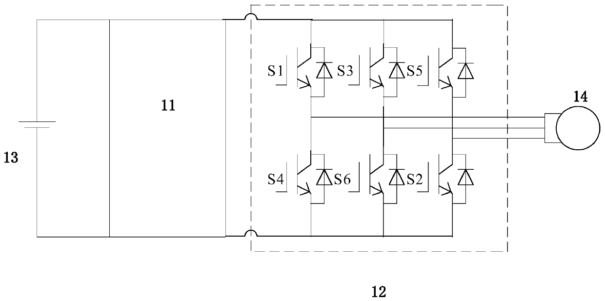
[0038] figure 1 It is a schematic diagram of a boosting system implemented based on an inverter in some embodiments of the present disclosure.

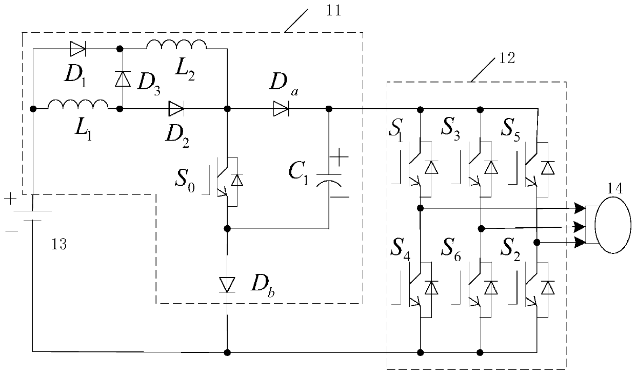
[0039] figure 2 It is a schematic diagram of a boosting system implemented based on an inverter in other embodiments of the present disclosure.

[0040] Such as figure 1 and figure 2 As shown, the boost system of this embodiment includes: a pre-stage circuit 11 and an inverter bridge 12 , and may also include a DC input power source 13 and a load (such as a motor load, etc.) 14 . Wherein, the front stage circuit 11 and the inverter bridge 12 form an inverter.

[0041] Such as figure 1 and figure 2 As shown, the inverter bridge 12 can be composed of upper and lower bridge arms, for example, a three-phase inverter bridge is ...


PUM


Abstract

The invention presents an inverter and a boost control method and control device thereof, and a front-stage circuit, which relate to the field of electronic circuits. Through a front-stage circuit with a set structure, the voltage of a single-stage inverter can be adjusted. In addition, by reasonably setting the direct proportion of the inverter bridge, the voltage of the inverter can be boosted by any multiple. Through the setting of a front-stage circuit structure and an energy storage element thereof, the upper and lower bridge arms of the inverter can be directly connected without inserting dead time, the output waveform is improved, and the quality of the output voltage is improved.

Description

technical field [0001] The present disclosure relates to the field of electronic circuits, and in particular to an inverter, its boost control method and control device, and a pre-stage circuit. Background technique [0002] An inverter is a device that converts direct current into alternating current. One of the voltage-type inverters, if it is used in a situation where the input voltage range changes greatly, needs to add a DC / DC (direct current to direct current) converter in the front stage. The multi-stage structure will reduce the transmission efficiency of the system and increase the cost. [0003] In addition, the voltage-type inverter does not allow the upper and lower bridge arms to be turned on at the same time, otherwise a short circuit will occur and the inverter will be damaged. The addition of dead time will cause distortion of the output waveform. Contents of the invention [0004] In order to solve at least one of the above-mentioned problems of the volt...

Claims


Application Information

Patent Timeline
Patent Type & Authority Applications(China)
IPC IPC(8): H02M7/5387H02M3/156
CPCH02M3/156H02M7/53871H02M1/007
Inventor 贺小林李修贤郑嘉良王双骥杨智雄
Owner GREE ELECTRIC APPLIANCES INC
Why Eureka
Try Eureka