Locking assembly, embedded cooktop and installation method

An installation method and embedded technology, applied in the field of cookers, can solve the problems of shielding and covering the reserved holes, the cooker cannot be embedded normally, and it is difficult to realize convenient locking and fitting, etc., so as to achieve the effect of avoiding exposure.

Pending Publication Date: 2019-08-09
宁波神力燃具有限公司
View PDF0 Cites 0 Cited by
  • Summary
  • Abstract
  • Description
  • Claims
  • Application Information

AI Technical Summary

Problems solved by technology

[0005] When assembling the front operation panel, due to the structural limitations of the locking parts used, that is, the lock buckle and the threaded sleeve, and the front operation panel itself caters to the assembly of the locking parts, and its own structural limitations, resulting in When using the locking parts to assemble the front operation panel on the fitting part, the operator needs to perform alignment operations on the front operation panel, the lock, and the threaded sleeve at all times, so that the operator needs to straighten the front operation panel while locking the threaded sleeve , it is difficult to achieve convenient locking assembly
In addition, not only the locking parts, but also the front operation panel are matched with each other, the overall structure is more complicated and cumbersome, especially the front operation panel, due to the limitation of its structural size, needs to be manufactured and shaped before leaving the factory to match the assembly part. In this way, when the size of the reserved hole at the upper end of the front of some cabinets does not match the length of the fitting part, that is, when the length of the fitting part is much smaller than the length of the reserved hole, even if it is fitted on the fitting part Operation panel, but because the size and length of the front operation panel match the length of the fitting part, the front operation panel cannot cover all the reserved holes, so that the entire cooker cannot be installed normally, which weakens the versatility of the cooker

Method used


Image

  • Locking assembly, embedded cooktop and installation method
  • Locking assembly, embedded cooktop and installation method
  • Locking assembly, embedded cooktop and installation method

Examples


Embodiment Construction

[0040] The present invention will be further described below in conjunction with the accompanying drawings and specific embodiments.

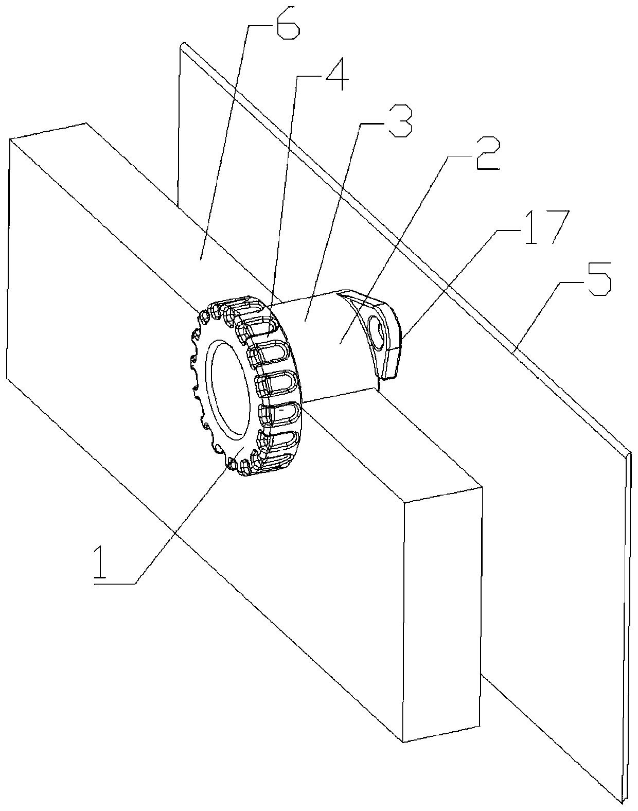
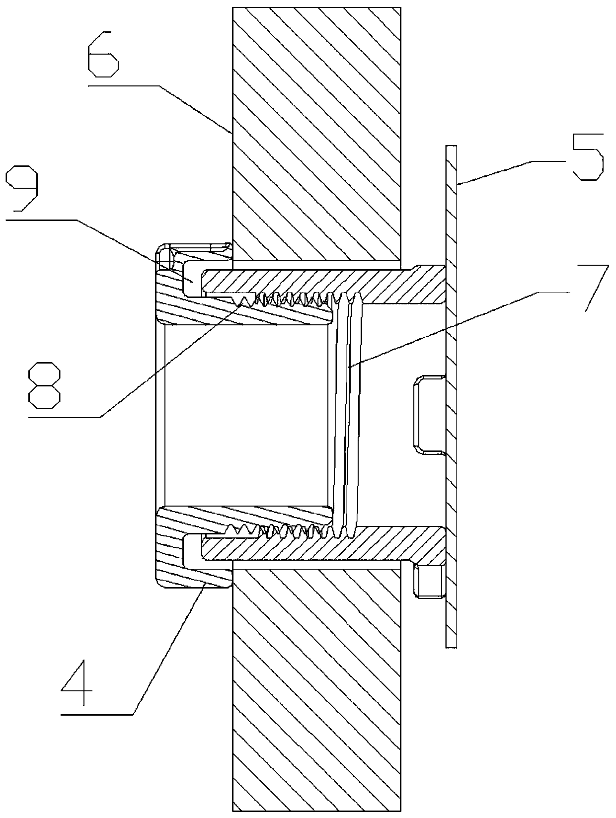
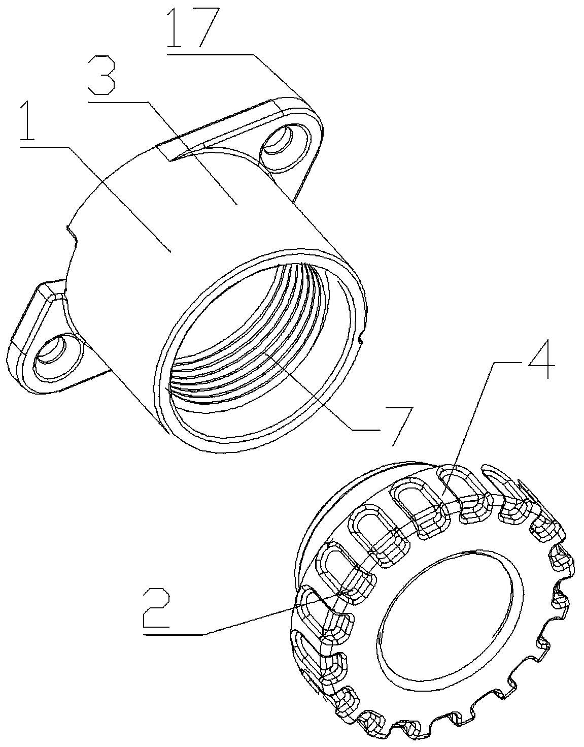
[0041] in figure 1 It is a structural schematic diagram of a locking assembly in use according to the present invention (parts of the second carrier have been removed to facilitate the display of other components). figure 2 It is a schematic cross-sectional structural diagram of a locking assembly in use according to the present invention. image 3 It is a schematic diagram of an exploded structure in a first orientation of a locking assembly of the present invention. Figure 4 It is a schematic diagram of an exploded structure in a second orientation of a locking assembly of the present invention. Figure 5 It is a structural schematic diagram of the first orientation of the built-in cooker with the locking assembly applied in the present invention (the part of the front operation panel has been removed to facilitate the display of other co...


PUM


Abstract

The invention discloses a locking assembly. The locking assembly comprises a first locking body and a second locking body which are provided with hole bodies; the threaded screw connection of the first locking body and the second locking body is realized by the hole bodies; the first locking body is assembled on a first carrier; a second carrier sleeving part is assembled on the first locking body; and the second locking body is provided with a pressing part so as to press and lock the second carrier during the threaded screw process. After the locking assembly is used for the embedded cooktop, the first locking body is installed on an external convex assembly part; the first locking body is fitted with a front operation panel pressing the second locking body; the second locking body is inthreaded screw with the first locking body so that the front operation panel is locked and fixed on a frame body of a reserved hole at the upper end of the front part of a cabinet, and an air inlet passage is left between the top of the front operation panel and the upper frame part of the frame body. The locking assembly can lock and fix the front operation panel conveniently, and the fixed front operation panel can be adapted to reserved holes at the upper ends of cabinets with different sizes.

Description

technical field [0001] The invention relates to the technical field of cooking appliances, in particular to a locking assembly, an embedded cooking appliance equipped with the locking assembly, and an installation method for locking and fixing a front operation panel of the embedded cooking appliance by using the locking assembly. Background technique [0002] The existing type embedded cooker generally includes a cooker panel, a fire distributor, a burner, a valve body and a bottom case. Among them, the operating elements, such as the switch (knob type or touch type) for controlling the action of the burner, and the timer (non-touch type or touch type) for controlling the combustion time of the gas in the burner, etc. are generally arranged on the cooker panel. After the operating elements are installed on the cooker panel, they will be touched during cleaning, so it is not easy to clean the position near the knob, and oil and water can easily enter the cooker cavity from t...

Claims


Application Information

Patent Timeline
Patent Type & Authority Applications(China)
IPC IPC(8): F16B5/02A47B77/08F23L1/00F24C3/12F24C15/00
CPCF16B5/02A47B77/08F24C15/00F24C3/126F23L1/00
Inventor 李力
Owner 宁波神力燃具有限公司
Why Eureka
Try Eureka