A method for controlling the system pressure of a centrifugal air compressor station

A system pressure and control method technology, applied in pump control, non-variable pumps, machines/engines, etc., can solve problems such as waste of air release, untimely response, large fluctuations in system pressure, etc., to maintain system pressure stability, Avoid invalid output and reduce the effect of system pressure fluctuation range

Active Publication Date: 2020-05-05
杭州全能星科技有限公司
View PDF8 Cites 0 Cited by
  • Summary
  • Abstract
  • Description
  • Claims
  • Application Information

AI Technical Summary

Problems solved by technology

[0007] The above control methods are still based on independent automatic adjustment of a single air compressor and remote or on-site manual intervention. For multiple air compressors running at the same time, the air compressor with a strong effect will cause the air compressor with a weak effect to surge first. limit, resulting in unnecessary waste of air release, and under the working conditions where the user's demand for compressed air volume fluctuates greatly, the independent adjustment of the single machine and manual intervention often do not respond in time, resulting in large fluctuations in the pressure of the external system of the air compressor station

Method used


Image

  • A method for controlling the system pressure of a centrifugal air compressor station
  • A method for controlling the system pressure of a centrifugal air compressor station
  • A method for controlling the system pressure of a centrifugal air compressor station

Examples


Embodiment

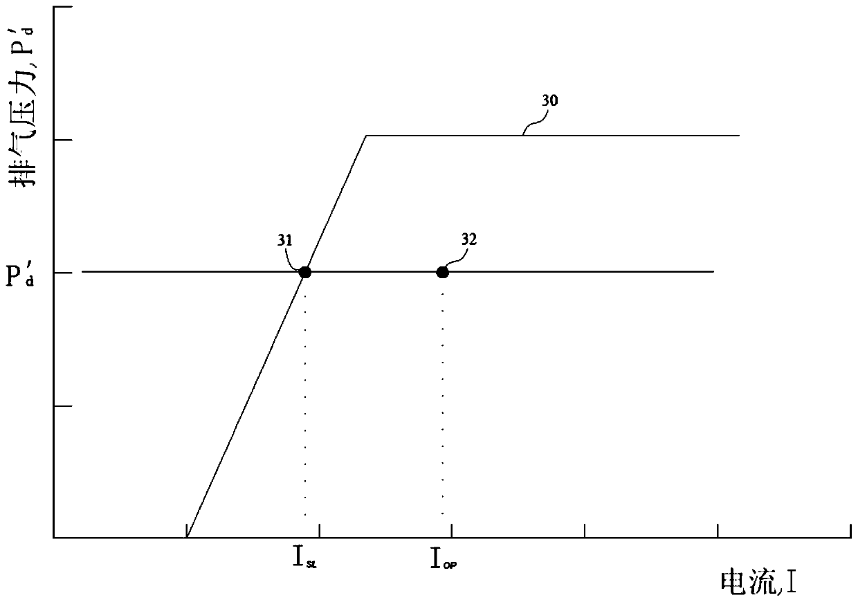
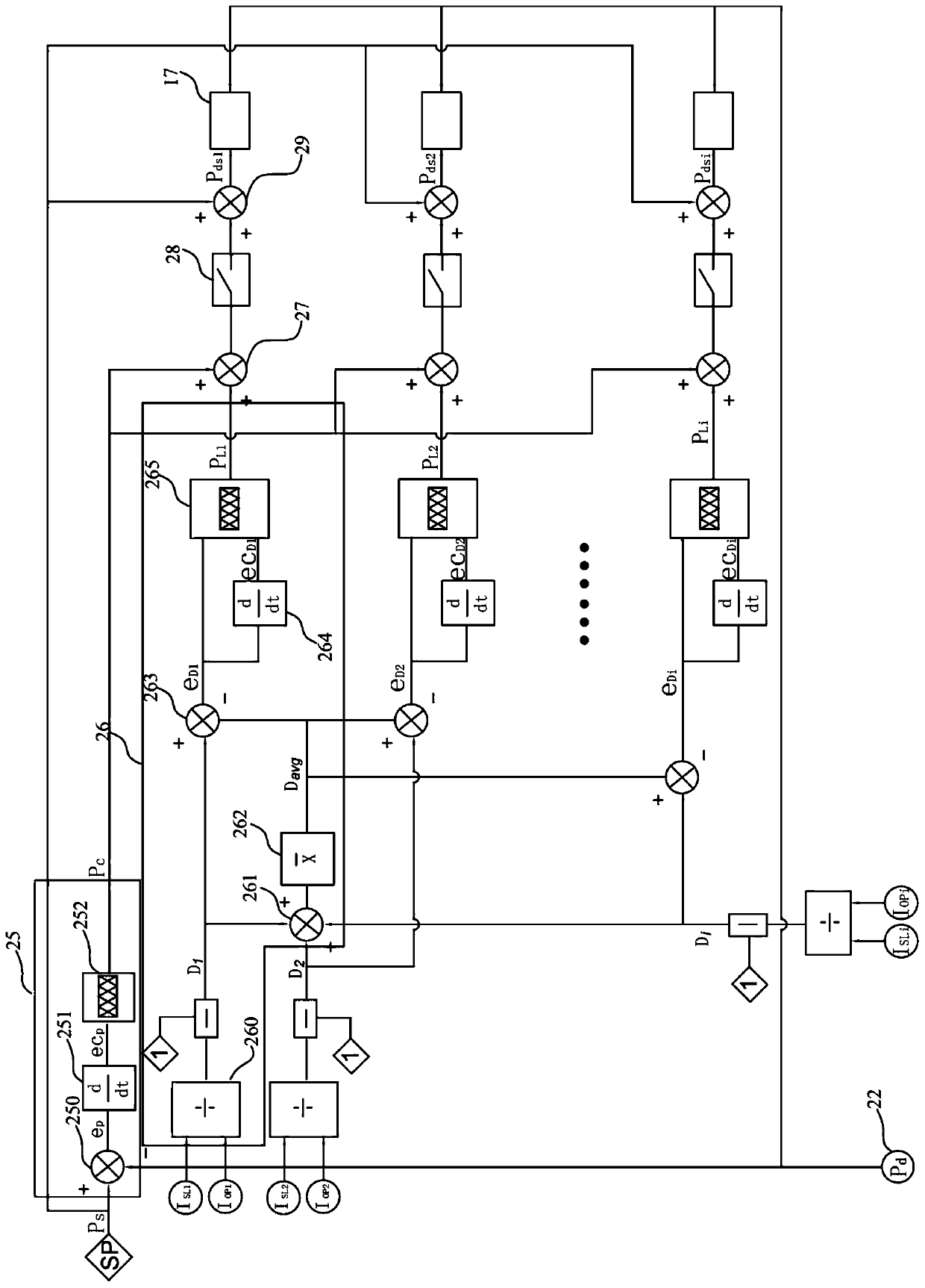
[0032] Example: as attached figure 1 Shown is the model diagram of the compression system of multiple centrifugal air compressors connected in parallel in the present invention, and the shown parallel connection compressor units A, B, ..., I are controlled by the centralized control system 24 and the on-site PLC of each compressor unit Station 17 is controlled, wherein the capacity of some compressor units may be different, but the structure of each compressor unit is the same (in this embodiment, all take the form of motor-driven compressors as an example), and have the same composition. One compressor unit includes an on-site PLC control station 17. Compressor body 10, drive motor 11, current sensor 18, exhaust branch pipe 16, exhaust valve 13, check valve 14 and branch pipe pressure sensor 19, the output end of the drive motor 11 is connected to the compressor body 10, and the The current sensor 18 is connected to the driving motor 11, the suction side of the compressor bod...


PUM


Abstract

The invention discloses a control method and a control system for the system pressure of a centrifugal air compression station, and relates to centrifugal air compression station output system pressure control and load compensation control of each compressor unit in the air compression station. The control system comprises a centralized control system, wherein the centralized control system and acompressor unit field programmable logic controller (PLC) control station are in double-way connection; the centralized control system comprises a system pressure change compensation module, a load compensation module and a power limit control module; a remote pressure setting instruction is that Pds is equal to PS+PC+PL; a remote pressure setting instruction Pds input field PLC control station isused as a setting point; whether each compressor exceeds the limit or not is judged according to preset limiting power value of power of each compressor unit in the air compression station; and if the compressors exceed the limit, an inlet guide vane and an exhaust valve of each compressor unit are controlled through the field PLC control station, so that each compressor unit is ensured to outputan appropriate load. The control method and the control system for the system pressure of the centrifugal air compression station provided by the invention solve the technical problems how to controlthe pressure of a user air supply system to be stable, enable each compressor unit in the air compression station to bear the appropriate load, and reduce the energy consumption.

Description

technical field [0001] The invention relates to the field of centralized management and control of a centrifugal air compressor station, in particular to a method for controlling system pressure of a centrifugal air compressor station. Background technique [0002] As one of the four fluid media (water, compressed air, steam and natural gas) used in industrial production, compressed air is widely used because of its safety, cleanliness and ease of control, and plays a pivotal role in industrial production. At present, large-scale factories and industrial parks have established air compressor stations for centralized air supply. Each air compressor station generally consists of several or even more than a dozen air compressors. The types of air compressors used are mainly screw air compressors. And centrifugal air compressors, among which centrifugal air compressors are more and more widely used in air compressor stations due to their high efficiency and large capacity. [0...

Claims


Application Information

Patent Timeline
Patent Type & Authority Patents(China)
IPC IPC(8): F04D27/02F04D27/00
CPCF04D27/00F04D27/02
Inventor 鲍献忠纪云锋屠昌锋吴康东方韬黄国锋
Owner 杭州全能星科技有限公司
Why Eureka
Try Eureka