Carrier tape head end shifting and positioning mechanism for carrier tape automatic winding and collecting system

A technology of positioning mechanism and winding mechanism, which is applied in the direction of winding strips, thin material processing, transportation and packaging, etc., which can solve the problems that the carrier tape cannot be reliably wound, and the head end of the carrier tape cannot be effectively positioned, so as to achieve reliable positioning , to avoid loose effect

Pending Publication Date: 2019-08-09
无锡山藤精密科技有限公司
View PDF0 Cites 2 Cited by
  • Summary
  • Abstract
  • Description
  • Claims
  • Application Information

AI Technical Summary

Problems solved by technology

[0003] In view of the above problems, the present invention provides a carrier tape head end toggle positioning mechanism for the carrier tape automatic winding and rewinding system, which can solve the problems caused by the inability to effectively position the carrier tape head in the existing carrier tape automatic winding and rewinding system. Problems that prevent carrier tape from being reliably wound

Method used


Image

  • Carrier tape head end shifting and positioning mechanism for carrier tape automatic winding and collecting system
  • Carrier tape head end shifting and positioning mechanism for carrier tape automatic winding and collecting system
  • Carrier tape head end shifting and positioning mechanism for carrier tape automatic winding and collecting system

Examples


Embodiment Construction

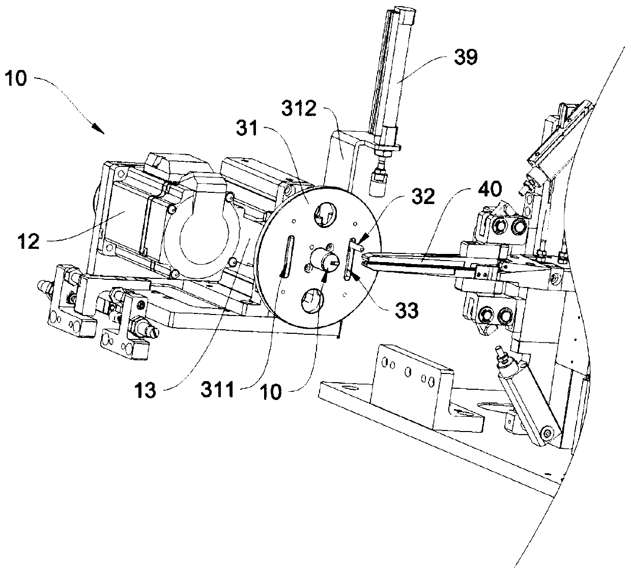
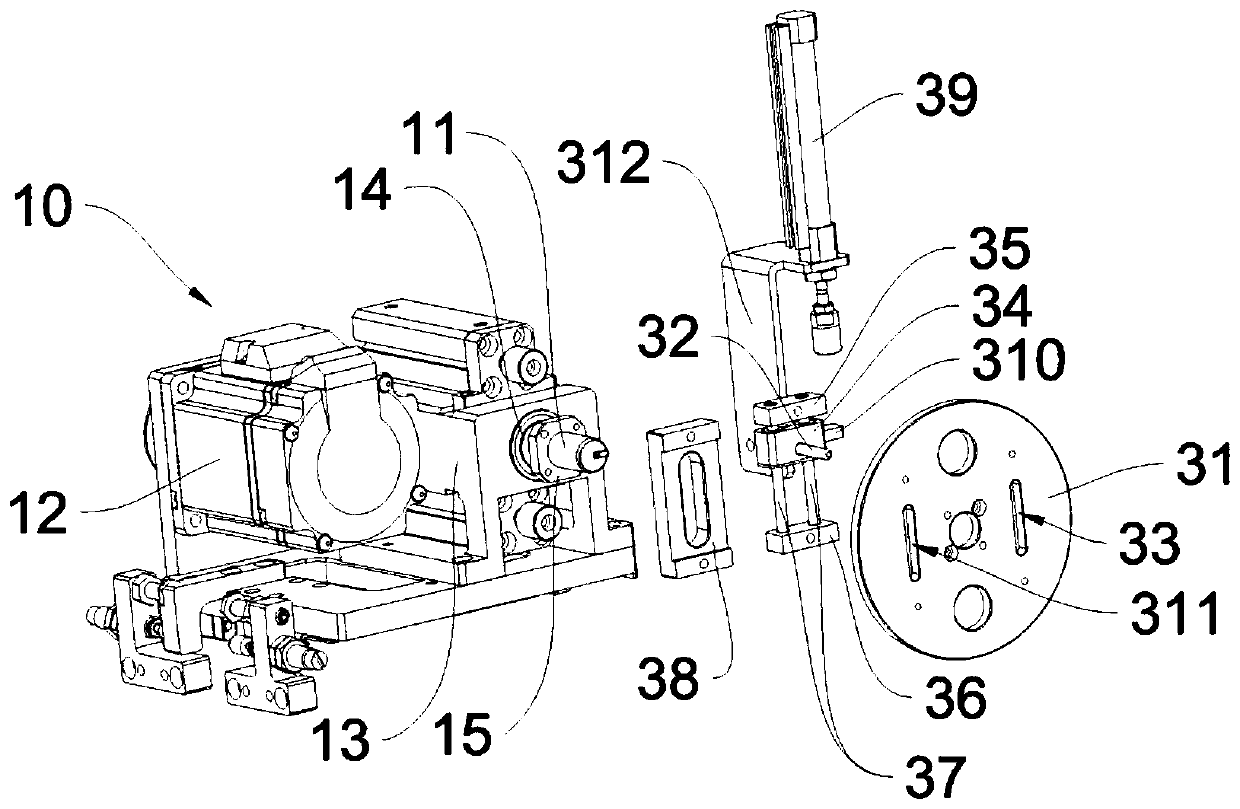
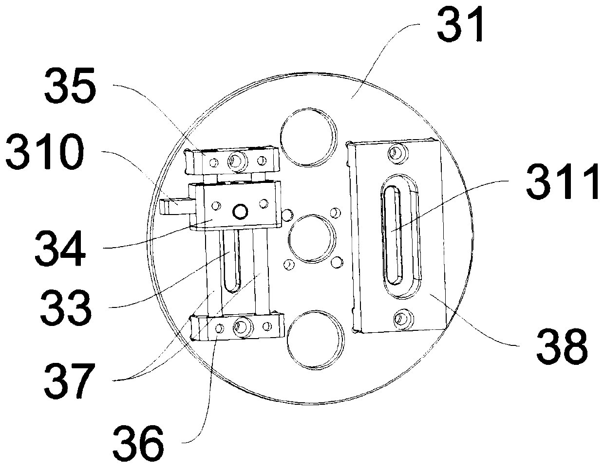
[0017] See figure 1 , the present invention is used for the carrier tape head end toggle positioning mechanism of the carrier tape automatic winding system, the carrier tape automatic winding system includes a winding mechanism 10, and the winding mechanism 10 includes a winding shaft 11 and a winding motor 12, The reel 20 is detachably mounted on the reel 11 through its central axis hole 21, and the reel 12 can drive the reel 11 to drive the reel 20 to rotate. In this embodiment, the reel 12 drives the reel through a synchronous sprocket 11 rotation; it also includes a toggle positioning base plate 31, a dial needle 32 and a toggle drive assembly, the winding shaft 11 runs through the toggle positioning base plate 31 from the back to the front, and the reel 20 for winding the carrier tape passes through its central shaft hole 21 is installed on the protruding end of the rewinding shaft 11 protruding on the dial positioning base plate 31, and a vertical dialing groove 33 is p...


PUM


Abstract

The invention provides a carrier tape head end shifting and positioning mechanism for a carrier tape automatic winding and collecting system. The mechanism can solve the problem that a carrier tape cannot be reliably wound due to the fact that the head end of the carrier tape cannot be effectively positioned in an existing system. The mechanism comprises a shifting positioning base plate, a shifting needle and a shifting driving assembly, wherein a winding shaft penetrates through the center of the shifting positioning base plate in a penetrating manner from back to front, a reel is arranged on the extending end of the shifting positioning base plate in front of the winding shaft, a vertical shifting groove is formed in shifting positioning base plate and in the right side of the winding shaft, when the head end of the carrier tape is conveyed into a carrier tape head end limiting hole, the vertical shifting groove communicates with the carrier tape head end limiting hole, the shiftingneedle penetrates through the vertical shifting groove from the back to the front and can extend into the carrier tape head end limiting hole, and when the head end of the carrier tape is conveyed into the carrier tape head end limiting hole through a carrier tape head feeding inlet, the driving assembly can be shifted to drive the shifting needle to move downwards along the vertical shifting groove, and meanwhile, the shifting needle is used for pressing and fixing the carrier tape head end extending into the carrier tape head end limiting hole along the carrier tape head feeding inlet.

Description

technical field [0001] The invention relates to the field of automation equipment, in particular to a carrier tape head end toggle positioning mechanism used in a carrier tape automatic winding and rewinding system. Background technique [0002] After the packaging and testing of electronic components is completed, the electronic components are put into the orderly arranged carrier tape pockets through the tape braiding equipment, and then sealed with the cover tape. inside the reel. Usually when the carrier tape is wound on the winding shaft 26 between the front baffle 24 and the rear baffle 25 of the empty reel 20 by the winding and rewinding system (the structure of the reel 20 is shown in Figure 5 ), it is necessary to send the head end of the carrier tape to the carrier tape head limit hole 22 of the empty reel through the tape carrier inlet 23 on the reel 26 by the carrier tape head pinch mechanism 40, and then wind the material The winding mechanism 10 of the system...

Claims


Application Information

Patent Timeline
IPC IPC(8): B65H18/10B65H19/28
CPCB65H18/10B65H19/28B65H2701/1944Y02P70/50
Inventor 张丰刘倩夏斌斌周峰华姜文林邹梦琦
Owner 无锡山藤精密科技有限公司
Why Eureka
Try Eureka