
Wind turbine temperature dependent noise reduction

一种风力涡轮机、涡轮机的技术,应用在风力发动机的控制、风力发动机、发动机等方向

Inactive Publication Date: 2019-08-06
VESTAS WIND SYST AS
View PDF4 Cites 0 Cited by
  • Summary
  • Abstract
  • Description
  • Claims
  • Application Information

AI Technical Summary

Problems solved by technology

This cooling fan makes noise

Method used


Image

  • Wind turbine temperature dependent noise reduction
  • Wind turbine temperature dependent noise reduction
  • Wind turbine temperature dependent noise reduction

Examples


Embodiment Construction

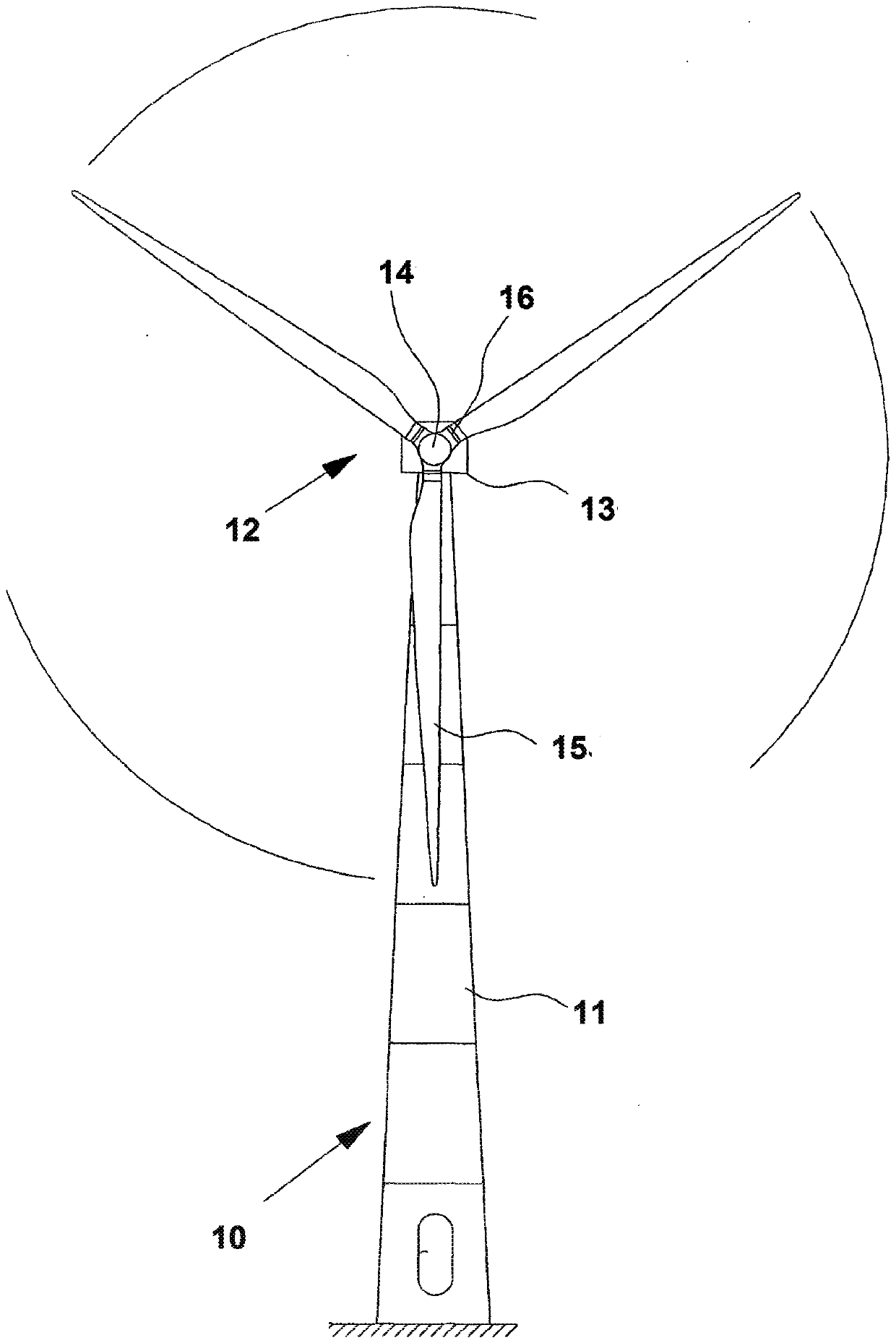
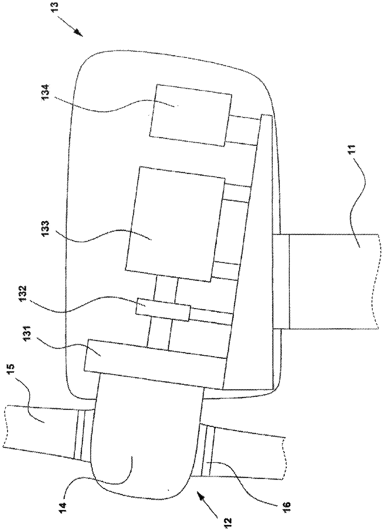
[0029] figure 1 A large modern wind turbine 10 known in the art is shown comprising a tower 11 and a wind turbine nacelle 13 on top of the tower. The wind turbine blades 15 of the turbine rotor 12 are mounted on a common hub 14 connected to the nacelle 13 by a low speed shaft extending from the front of the nacelle. The wind turbine blades 15 of the turbine rotor 12 are connected to the hub 14 by pitch bearings 16 such that the blades can rotate about their longitudinal axes. The pitch angle of the blades 15 can then be controlled by linear actuators, stepper motors or other means for rotating the blades. The illustrated wind turbine 10 has three turbine blades 15, but it is understood that the wind turbine may have another number of blades, such as one, two, four, five or more.

[0030] The wind turbine may also include a wind turbine controller positioned on or within the turbine or at a remote location from the turbine. A controller may be communicatively coupled to any ...


PUM


Abstract

A method of controlling noise produced by a wind turbine is disclosed. The wind turbine comprises one or more component cooling devices, and the method comprises: receiving one or more inputs indicative of noise generated by the one or more component cooling devices; determining the contribution of noise from the one or more component cooling devices to overall turbine noise based upon the one ormore inputs; and modifying turbine operation based upon the contribution of cooling device noise to overall turbine noise and based upon turbine noise requirements. A corresponding wind turbine controller is also provided.

Description

technical field [0001] The present invention relates to controlling noise generated by wind turbines. Background technique [0002] Noise emissions from wind turbines are a well-known problem and have been the subject of extensive work. The procedure for measuring the acoustic noise of wind turbines is described in the third edition of the international standard IEC61400-11. [0003] Noise emissions from wind turbines include both mechanical and aerodynamic noise. Mechanical noise includes noise driven by components within the nacelle, such as the wind turbine drive train. This noise can be radiated directly from the surface of the vibrating component to the surrounding environment (so-called airborne noise), or it can be radiated to the surrounding environment by the wind turbine tower or blades when the vibration of the component is conducted through the structure of the wind turbine (so-called structural noise). Propagated Noise SBN). Aerodynamic noise originates from...

Claims


Application Information

Patent Timeline
Patent Type & Authority Applications(China)
IPC IPC(8): F03D7/02F03D80/60
CPCF03D7/0296F05B2270/333F03D80/60Y02E10/72F03D80/82F03D7/0224
Inventor M·古普塔K·D·马德森
Owner VESTAS WIND SYST AS
Learn More