Method for evaluating surface drag reduction effect of different morphologies of microstructures based on numerical simulation
A numerical simulation and evaluation method technology, which is applied in the direction of electrical digital data processing, special data processing applications, instruments, etc., can solve the problems of high cost of special-shaped structures, long experimental period is difficult to evaluate, and it is difficult to obtain the influence law of drag reduction effect, etc., to achieve The effect of short cycle and low cost
- Summary
- Abstract
- Description
- Claims
- Application Information
AI Technical Summary
Problems solved by technology
Method used
Image
Examples
Embodiment 1
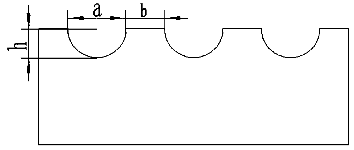
[0034] like figure 1 As shown, (1) Build the model: Use Icem software to build a fluid model on the surface of the two-dimensional semicircular pit-shaped microstructure. First establish the origin, and then establish nodes with the origin as the reference point. The overall size is 4mm in length and 1mm in width. , the size of the microstructure is groove width a=200 μm, protrusion width b=200 / 100 / 40 / 20 / 4 μm, groove depth h=100 μm.
[0035] (2) Mesh division: define the left end of the model as the entrance, the right end as the exit, and the others as the wall. Build and divide the model into blocks to ensure that each microstructure is regarded as an independent block. After dividing the blocks, the divided blocks and Correlate each part. After the correlation is completed, set the grid type at the microstructure to O-grid, and perform an encryption process on the grid near the wall. Set the grid density Spacing to 0.0001, and the growth rate Ratio to 1.2 to ensure that the...
Embodiment 2
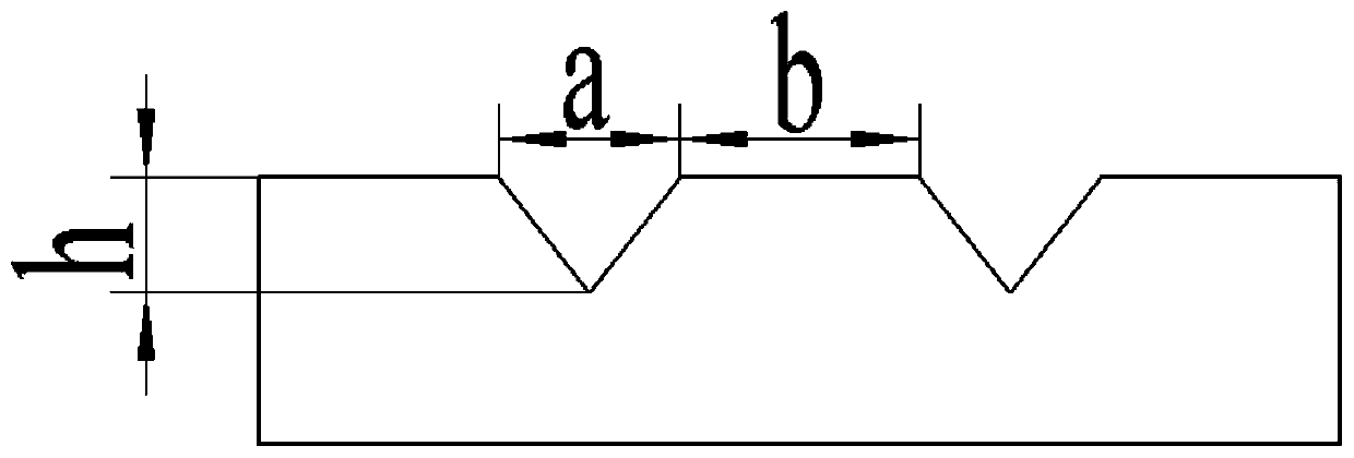
[0043] (1) Modeling: Use Icem software to construct a fluid model of a two-dimensional triangular microstructure surface. First establish the origin, and then establish nodes with the origin as a reference point. The overall size is 4 mm in length, 1 mm in width, and the microstructure size is Groove width a=200 μm, protrusion width b=200 / 100 / 40 / 20 / 4 μm, groove depth h=100 μm.
[0044] (2) Mesh division: Define the left end of the model as the entrance, the right end as the exit, and the others as the wall. Build and divide the model into blocks to ensure that each microstructure is an independent block. After dividing the blocks, divide the microstructure Adjust the nodes of the blocks, adjust the cross-shaped nodes into Y-shaped nodes, and associate the blocks after adjusting the nodes with each part. After the association is completed, set the Y-shaped grid at the microstructure, and set the quadrilateral grid at other parts. Encrypt the grid near the wall, set the grid den...
PUM
 Abstract
Description
Claims
Application Information
 - Generate Ideas
- Intellectual Property
- Life Sciences
- Materials
- Tech Scout
- Unparalleled Data Quality
- Higher Quality Content
- 60% Fewer Hallucinations
Browse by: Latest US Patents, China's latest patents, Technical Efficacy Thesaurus, Application Domain, Technology Topic, Popular Technical Reports.
© 2025 PatSnap. All rights reserved.Legal|Privacy policy|Modern Slavery Act Transparency Statement|Sitemap|About US| Contact US: help@patsnap.com


