Double-working-surface integrated bridge girder erection machine without front supporting legs

A bridge erecting machine and double-working technology, which is applied in the direction of erecting/assembling bridges, bridges, bridge construction, etc., can solve the problems of poor adaptability, reduced work efficiency, and many processes, so as to achieve high erection efficiency, improve operation efficiency, and improve adaptability sexual effect

Pending Publication Date: 2019-08-06
ZHEJIANG PROVINCIAL INST OF COMM PLANNING DESIGN & RES CO LTD
View PDF0 Cites 4 Cited by
  • Summary
  • Abstract
  • Description
  • Claims
  • Application Information

AI Technical Summary

Problems solved by technology

[0007] As mentioned above, this double-face integrated bridge erecting machine has poor adaptability in areas with large terrain fluctuations. Since the front outrigger 2 of the bridge erecting machine is supported on the pier cap (bottom tie beam) 9, each It is necessary to adjust the height of the front outrigger column 2 (a) in one span of construction to adapt to the pier cap (bottom tie beam) 9 of different elevations, which reduces the work efficiency
Moreover, a fixing device needs to be provided between the front outrigger 2 and the pier cap (bottom tie beam) 9. When hoisting the pier column 8 and the cover beam 7, the front outrigger 2 needs to be fixed, but the construction of the superstructure main girder 6, you need to release the fixation to meet the lateral movement of the bridge erecting machine, and there are many procedures

Method used


Image

  • Double-working-surface integrated bridge girder erection machine without front supporting legs
  • Double-working-surface integrated bridge girder erection machine without front supporting legs
  • Double-working-surface integrated bridge girder erection machine without front supporting legs

Examples


Embodiment Construction

[0028] In order to describe the present invention more specifically, the technical solutions of the present invention will be described in detail below in conjunction with the accompanying drawings and specific embodiments.

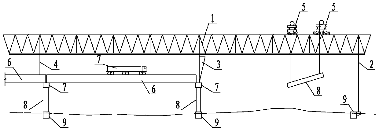
[0029] The present invention provides an integrated bridge-erecting machine with double working surfaces without front outriggers. The bridge-erecting machine itself is fully supported on the erected girder spans, so it is not affected by the undulating terrain and has strong adaptability. , The erection efficiency is high, and its structural layout is as follows image 3 , Figure 4 , Figure 5(a), Figure 5(b).

[0030] Such as image 3 As shown, the main basic components of this dual-face integrated bridge erecting machine without front outriggers mainly include: main truss 1, cable tower 2 and cable 3, front load-bearing outrigger 4, auxiliary outrigger 5, rear Bearing leg 6 and crane 11.

[0031] Such as Figure 4 As shown, the main truss 1 is a t...


PUM


Abstract

The invention discloses a double-working-face integrated bridge girder erection machine without front supporting legs. An existing double-working-surface integrated bridge girder erection machine is improved, front supporting legs are cancelled, and a 'cantilever' part at the front part of the bridge grinder erection machine is supported by stay cables, so the whole bridge girder erection machineis supported on an erected girder span without being influenced by undulating topography, and can erect bridge prefabricated parts, so the operation efficiency is improved, previous procedures of repeatedly fixing and unlocking front supporting legs and repeatedly adjusting the heights of front supporting leg stand columns are omitted, the construction procedures are simplified, and the erection efficiency and the adaptability of the bridge grinder erection machine are improved. Meanwhile, the integrated bridge girder erection machine can achieve full-prefabricated integrated shortcut-free transportation and assembly erection of the bridge pier stand columns, the cover beams and the upper part structure main beams, is high in adaptability and erection efficiency and can adapt to full-prefabricated assembly of bridges in areas with large topography fluctuation such as mountainous areas, and hills.

Description

technical field [0001] The invention belongs to the technical field of bridge engineering, and in particular relates to a double-working surface integrated bridge erecting machine without front outriggers. Background technique [0002] The concrete structure can adopt cast-in-place and prefabricated construction. The girders and slabs of conventional elevated bridges (such as T beams, combined small box girders and hollow slabs) generally adopt prefabricated assembly construction, while the pier columns and cover beams in the substructure are all cast-in-situ construction. The traditional cast-in-place construction technology of pier columns and cap beams has high cost, high risk, and difficult quality assurance due to many high-altitude operations. In bustling urban areas, cast-in-place construction will have adverse effects on surrounding traffic and environmental protection, and the contradictions are more prominent. [0003] In order to shorten the construction period,...

Claims


Application Information

Patent Timeline
Patent Type & Authority Applications(China)
IPC IPC(8): E01D21/00
CPCE01D21/00
Inventor 李磊庄万律魏益峰王昌将陈向阳
Owner ZHEJIANG PROVINCIAL INST OF COMM PLANNING DESIGN & RES CO LTD
Why Eureka
Try Eureka