Turnover device and vehicle manufactured by adopting turnover device
A technology of a turning device and a push rod device, which is applied in the direction of vehicles, vehicle parts, transportation and packaging including human living utensils, which can solve the problems of reducing the operating intensity, not being able to achieve easy operation, and high operating intensity, so as to improve automation horizontal effect
- Summary
- Abstract
- Description
- Claims
- Application Information
AI Technical Summary
Problems solved by technology
Method used
Image
Examples
Embodiment 1
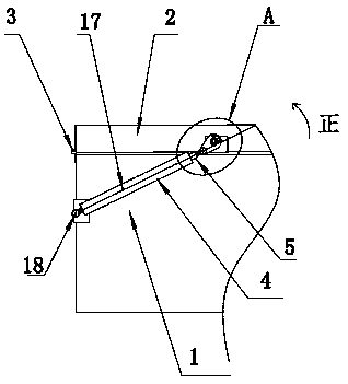
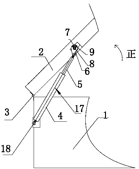
[0034] as attached figure 1 As shown, a turning device includes a fixed body 1 and a turning body 2, the turning body 2 and the fixing body 1 are hinged by a hinge 3, and the turning body 2 can produce 180° back and forth turning relative to the fixing body 1.
[0035] as attached figure 1 As shown, it also includes a push rod device. In this embodiment, the push rod device adopts an electric push rod 4, the bottom end of the electric push rod 4 is hinged with the hinge point 18 of the fixed body, and the electric push rod 4 can be wound around the fixed body 1. The fixed body hinge point 18 rotates.
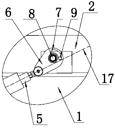
[0036] as attached figure 1 As shown, the telescopic rod 5 of the electric push rod 4 is connected to the reversing body 2 through a stress point offset device. The structure of the stress point offset device is shown in the attached figure 2 As shown, it includes a pin shaft 8 and a card shaft 9 fixed on the turning body 2 . It also includes a deflector 6. In this embodim...
Embodiment 2
[0049] In this embodiment, further modifications are made to the stress point offset device.
[0050] as attached Figure 11 As shown, in this embodiment, a pin shaft 8 and a limiting groove 7 are set on the turning body 2, combined with the attached Figure 12 As shown, the deflection body 6 is provided with a clamping shaft 9 , a hinge hole 11 , and a pin shaft through hole 12 . as attached Figure 13 As shown, after assembly, the pin shaft 8 passes through the pin shaft hole 12, the clamp shaft 9 passes through the limiting groove 7 on the turning body 2, and the bottom end of the deflection body 6 is hinged to the top end of the telescopic rod through the hinge hole 11. It can also achieve the effect of shifting the stress point achieved in Embodiment 1, and ensure that the reversing body performs 180° back and forth reversing.
[0051] In addition, as attached Figure 11 As shown, for the convenience of installation, the fixed plate 14 can be fixed on the turning body...
PUM
 Abstract
Description
Claims
Application Information
 - R&D
- Intellectual Property
- Life Sciences
- Materials
- Tech Scout
- Unparalleled Data Quality
- Higher Quality Content
- 60% Fewer Hallucinations
Browse by: Latest US Patents, China's latest patents, Technical Efficacy Thesaurus, Application Domain, Technology Topic, Popular Technical Reports.
© 2025 PatSnap. All rights reserved.Legal|Privacy policy|Modern Slavery Act Transparency Statement|Sitemap|About US| Contact US: help@patsnap.com


