
A feeding mechanism for injection molding with oscillating function

A technology of feeding mechanism and function, which is applied in the field of feeding mechanism for injection molding, can solve problems such as cumbersome angle adjustment, material condensation, troubles in use, etc., and achieve the effects of improving convenience, avoiding condensation, and expanding the scope of use

Active Publication Date: 2021-03-16
ANHUI KERUITE MOLDING CO LTD
View PDF8 Cites 0 Cited by
  • Summary
  • Abstract
  • Description
  • Claims
  • Application Information

AI Technical Summary

Problems solved by technology

[0004] 1. The traditional feeding mechanism of this type is generally not equipped with a vibration function for the material, which can easily lead to the condensation of the material;
[0005] 2. The adjustment effect of the traditional feeding mechanism is not ideal when it is used, which seriously affects the convenience of the feeding mechanism;
[0006] 3. The angle adjustment of the traditional feeding mechanism is cumbersome, which brings great troubles to people's use.

Method used


Image

  • A feeding mechanism for injection molding with oscillating function
  • A feeding mechanism for injection molding with oscillating function
  • A feeding mechanism for injection molding with oscillating function

Examples


Embodiment Construction

[0023] The technical solutions in the embodiments of the present invention will be clearly and completely described below with reference to the accompanying drawings in the embodiments of the present invention. Obviously, the described embodiments are only a part of the embodiments of the present invention, but not all of the embodiments. Based on the embodiments of the present invention, all other embodiments obtained by those of ordinary skill in the art without creative efforts shall fall within the protection scope of the present invention.

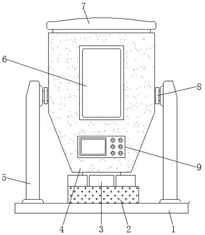
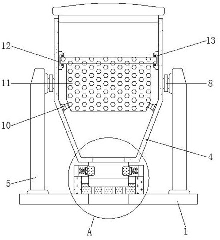
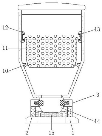
[0024] see Figure 1-4 , an embodiment provided by the present invention: a feeding mechanism for injection molding with oscillating function, including a base 1, a flow control cylinder 2, an arc-shaped fastening hoop 3, a hinged seat 8 and a control plate 15, the base 1 A flow control cylinder 2 is fixed at the top of the flow control cylinder 2, and a volume control plate 15 is installed on the inner side of the flow control cylind...


PUM


Abstract

The invention discloses an injection molding feeding mechanism with an oscillating function. The feeding mechanism comprises a base, a flow control cylinder, arc-shaped fastening hoops, a hinging seatand a quantity control disc, wherein the flow control cylinder is fixed at the top end of the base, the quantity control disc is arranged on the inner side of the flow control cylinder, the inner side walls of the arc-shaped fastening hoops are fixedly provided with compression springs at equal intervals, a feeding hopper is arranged above the flow control cylinder, a transparent window is inlaidin the center position of the surface of the feeding hopper, a control panel is fixed on the part, below the transparent window, of the surface of the feeding hopper, vibrating frames are fixedly arranged on the inner side walls of the feeding hopper, a vibrating hollowing-out cylinder is arranged on the inner sides of the vibrating frames inside the feeding hopper, the top end, above the vibrating hollowing-out cylinder, of the base is filled with a feeding cover, and a flow cylinder is fixed at the center of the bottom of the feeding hopper. According to the feeding mechanism, the condensation phenomenon of materials inside the feeding mechanism is avoided, the adjusting function of the discharging amount of the feeding mechanism is realized, and in addition, the using range of the feeding mechanism is expanded.

Description

technical field [0001] The invention relates to the technical field of injection molding, in particular to a feeding mechanism for injection molding with an oscillation function. Background technique [0002] Injection molding is a method for the production and modeling of industrial products. Usually, a feeding mechanism is often used in the process of injection molding. , locomotive and other industries. [0003] At present, there are many types of feeding mechanisms, but there are still some problems. The specific problems are as follows: [0004] 1. The traditional feeding mechanism of this type is generally not equipped with the vibration function of the material when it is used, which can easily cause the material to coagulate; [0005] 2. The traditional feeding mechanism of this type generally has an unsatisfactory effect of adjusting the amount of material discharged, which seriously affects the convenience of the feeding mechanism; [0006] 3. The angle adjustme...

Claims


Application Information

Patent Timeline
Patent Type & Authority Patents(China)
IPC IPC(8): B29C45/18
CPCB29C45/18
Inventor 查国东储振亚储亮李云雷程志刚
Owner ANHUI KERUITE MOLDING CO LTD
Learn More