Wide view angle receiving system based on APD array

An APD array and receiving system technology, applied in the field of visible light communication, can solve the problems of small imaging quality, reduced signal interference, low level, etc., and achieve the effect of increasing the photosensitive area

Inactive Publication Date: 2019-08-02
DONGGUAN XINDA INST OF INTEGRATED INNOVATION +1
View PDF6 Cites 2 Cited by
  • Summary
  • Abstract
  • Description
  • Claims
  • Application Information

AI Technical Summary

Problems solved by technology

2. Since the FOV of the convex lens is relatively small and the imaging quality is not high, the hemispherical lens cannot achieve omnidirectional reception, and the projected image is curved and large in size
SS means that there is a certain distance between each PD element in the PD array at the receiving end, so that the signal interference received by the PD is reduced, thereby reducing the correlation of the channel

Method used


Image

  • Wide view angle receiving system based on APD array
  • Wide view angle receiving system based on APD array
  • Wide view angle receiving system based on APD array

Examples


Embodiment Construction

[0024] The present invention will be described in further detail below in conjunction with the accompanying drawings and specific embodiments, and the implementation scope of the present invention is not limited thereto.

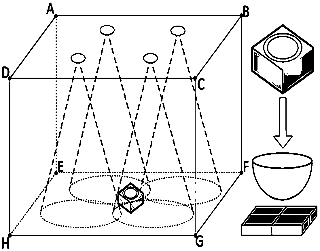
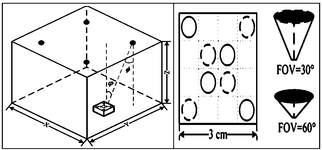
[0025] For a normal APD array, the field of view (FOV) of each of them is the same, but in order to reduce the correlation of the channel, the FOV of the PD can be different, such as image 3 , even if several PDs with different FOVs are used to form the receiving array, the PD with a large FOV can make the FOV of the PD array large enough, and the PD with a small FOV can reduce the channel correlation. It can also be added by adding some non-imaging optical devices, such as Compound parabolic concentrators, such as Figure 4 , light cone such as Figure 5 Wait.

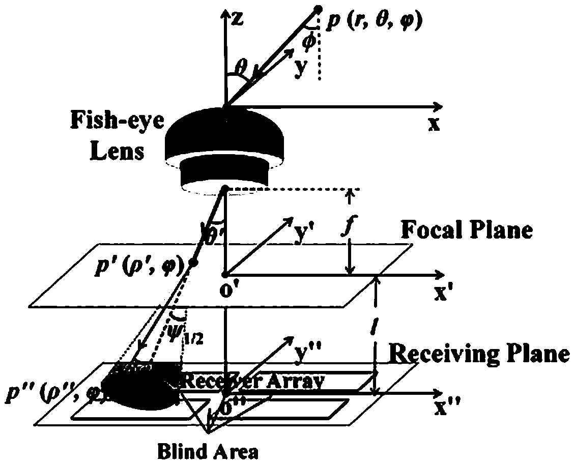
[0026] The main purpose of the present invention is to further enhance the communication quality while increasing the viewing angle of the receiver. Field of View (FOV) refers to the maximum ang...


PUM


Abstract

The invention discloses a wide view angle receiving system based on an APD array to achieve the above purpose. The wide view angle receiving system comprises a group of APD arrays, and each APD arraycomprises a central APD array element and a plurality of auxiliary APD array elements surrounding the central APD array element. Aiming at the problems of small receiver field angle, low mobility andthe like, the invention provides the APD array structure design and the signal receiving combination mode design, so that the communication quality is further enhanced while the receiver field angle is improved. According to the utility model, a 3 * 3 APD array is adopted as a receiver for visible light communication, so that the overall photosensitive area of the receiver is equivalently increased, and the photosensitive area of the receiver is equivalently improved through the array structure.

Description

technical field [0001] The invention relates to the field of visible light communication, in particular to a wide viewing angle receiving system based on an APD array. Background technique [0002] At present, the research on the VLC array receiving terminal is mainly focused on the receiving array on the relatively fixed same plane; there are two types of optical signal receiving arrays used by VLC, one is an image sensor (Camera), and the other is a PD array; With the rapid development of lighting and smart terminals embedded with cameras, imaging MIMO communication technology (Optical Camera Communication, OCC) based on existing image sensors is expected to be applied to many fields, such as between mobile phones and TV screens, street lights and cars, and between cars and cars communication, UAV auxiliary communication, etc. But the low frame rate of existing image sensors limits its application in high-speed communication. At present, the research on the receiving dis...

Claims


Application Information

Patent Timeline
Patent Type & Authority Applications(China)
IPC IPC(8): H04B10/69H04B10/67H04B10/116
CPCH04B10/116H04B10/671H04B10/691H04B10/693
Inventor 朱义君张海勇汪涛田忠骏郑晓东刘洛琨梁进山王小景
Owner DONGGUAN XINDA INST OF INTEGRATED INNOVATION
Why Eureka
Try Eureka