Passive optical network frame forming method, device and system
A passive optical network and framing technology, applied in the field of communication, can solve problems such as increased optical link loss and insufficient optical power budget
- Summary
- Abstract
- Description
- Claims
- Application Information
AI Technical Summary
Problems solved by technology
Method used
Image
Examples
Embodiment 1
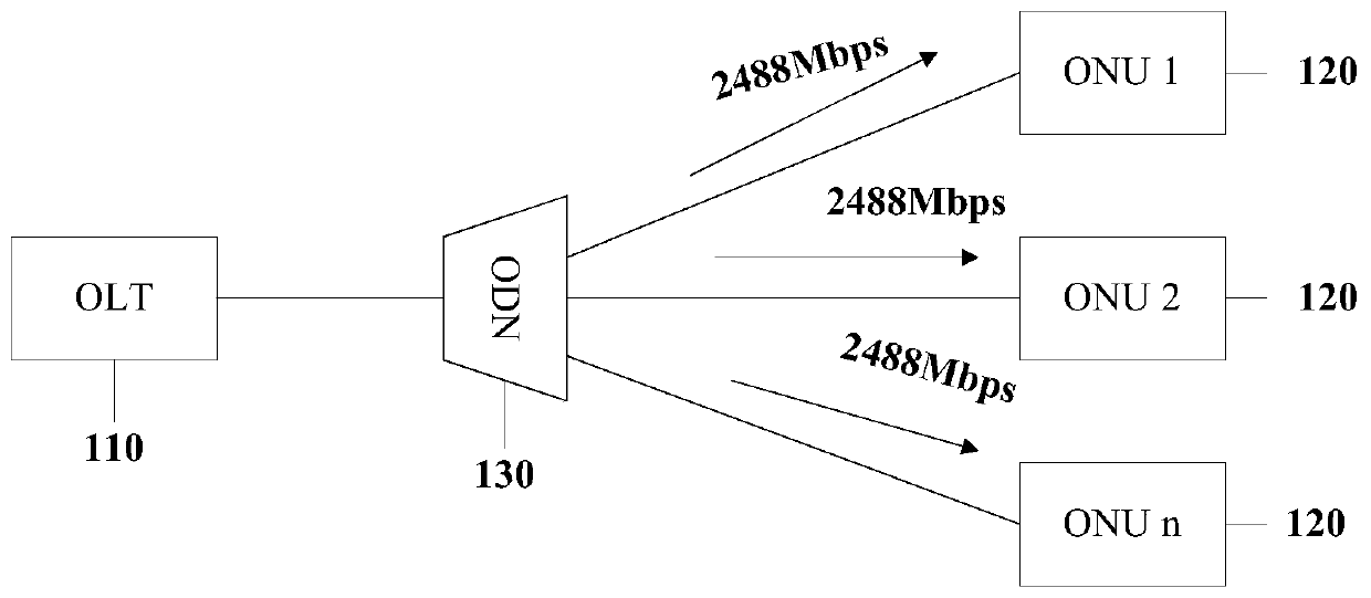
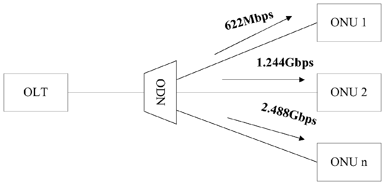
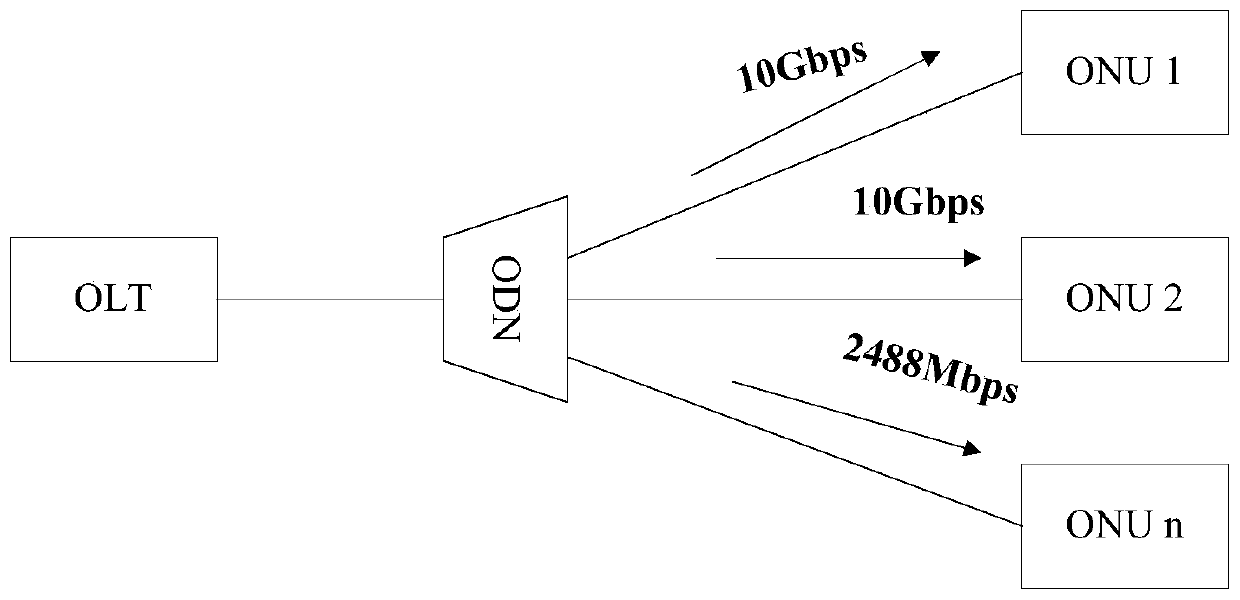
[0102] image 3 A schematic flowchart of a framing method provided by an embodiment of the present invention is shown, and the method is applied to such as Figure 2A or Figure 2B In the network structure shown, refer to image 3 As shown, the method includes:
[0103] Step 301, respectively generate a first TC frame and a second TC frame, wherein the downlink rate of the first TC frame complies with the standard G.984.3 or G.987.3, that is, 2.488Gbps or 10Gbps, and the downlink rate of the second TC frame The downlink rate is 1 / N of the downlink rate of the first TC frame, the sum of the frame lengths of the first TC frame and the second TC frame is 125 microseconds, and N is an integer greater than 1.
[0104] Step 302: Perform bit mapping on the second TC frame to generate a third TC frame, the bit mapping means that each bit of the second TC frame is identified by N bits.
[0105] Step 303, sending the first TC frame and the third TC frame to an ONU.
[0106] Prefera...
Embodiment 2
[0161] A method for framing a passive optical network provided by an embodiment of the present invention will be described in detail below with reference to FIG. 7 . As shown in FIG. 7, FIG. 7 shows a method 700 for framing provided by an embodiment of the present invention, and the method 700 includes:
[0162] S701. Generate a first TC frame and a second TC frame respectively, wherein the downlink rate of the first TC frame is 2.488Gbps or 10Gbps, and the downlink rate of the second TC frame is 1 / N of the downlink rate of the first TC frame , the sum of the frame lengths of the first TC frame and the second TC frame is 125 microseconds, and N is an integer greater than 1.
[0163] S702. Perform first encoding on the second TC frame. Among them, the first encoding can use RS (255,239), and can also use other encoding methods, such as RS (255,151) encoding, RS (248,216) encoding, LDPC encoding, concatenated FEC encoding, or other existing FEC encoding in the prior art , whic...
Embodiment 3
[0176] Figure 8 It shows a schematic flowchart of a method 800 for deframing a passive optical network provided by an embodiment of the present invention. The method 800 can be applied in GPON or XG-PON. When applied in a GPON system, the receiving rate is 2.488 Gbps ONU executes; when applied in XG-PON system, it is executed by ONU with receiving rate of 10Gbps. Such as Figure 8 As shown, the method 800 includes:
[0177] S801. Receive a downlink data stream, where the downlink data stream includes a first TC frame and a second TC frame, where the downlink rate of the first TC frame complies with the standard G.984.3 or G.987, that is, 2.488Gbps Or 10Gbps, the downlink rate of the second TC frame is 1 / N of the downlink rate of the first TC frame, the sum of the frame lengths of the first TC frame and the second TC frame is 125 microseconds, and N is an integer greater than 1.
[0178] S802. Synchronize with the first TC frame.
[0179] S803. Parse the first TC frame.
...
PUM
 Abstract
Description
Claims
Application Information
 - Generate Ideas
- Intellectual Property
- Life Sciences
- Materials
- Tech Scout
- Unparalleled Data Quality
- Higher Quality Content
- 60% Fewer Hallucinations
Browse by: Latest US Patents, China's latest patents, Technical Efficacy Thesaurus, Application Domain, Technology Topic, Popular Technical Reports.
© 2025 PatSnap. All rights reserved.Legal|Privacy policy|Modern Slavery Act Transparency Statement|Sitemap|About US| Contact US: help@patsnap.com


