
Shock wave energy passive measurement sensor based on thin-walled tube expansion energy absorption

A passive measurement, thin-walled tube technology, applied in the field of measurement and detection, can solve the problems of difficult wiring, electromagnetic interference, cumbersome processing procedures, etc., and achieve the effect of fast quantitative passive measurement

Active Publication Date: 2019-08-02
NAT UNIV OF DEFENSE TECH
View PDF6 Cites 4 Cited by
  • Summary
  • Abstract
  • Description
  • Claims
  • Application Information

AI Technical Summary

Problems solved by technology

[0008] The technical problem to be solved in the present invention is to provide a shock wave energy passive measurement sensor based on the expansion and energy absorption of thin-walled tubes, so as to solve the difficulties in wiring and electromagnetic interference in the electrical measurement active sensors used in the existing active measurement methods; In the existing passive measurement methods, the post-measurement processing procedures are cumbersome, or the measurement system is complex, or the shortcomings of electrical measurement equipment are required for auxiliary measurement

Method used


Image

  • Shock wave energy passive measurement sensor based on thin-walled tube expansion energy absorption
  • Shock wave energy passive measurement sensor based on thin-walled tube expansion energy absorption
  • Shock wave energy passive measurement sensor based on thin-walled tube expansion energy absorption

Examples


Embodiment Construction

[0035] In order to facilitate those skilled in the art to understand and implement the patent of the present invention, the present invention will be further described in detail below in conjunction with the accompanying drawings and specific embodiments.

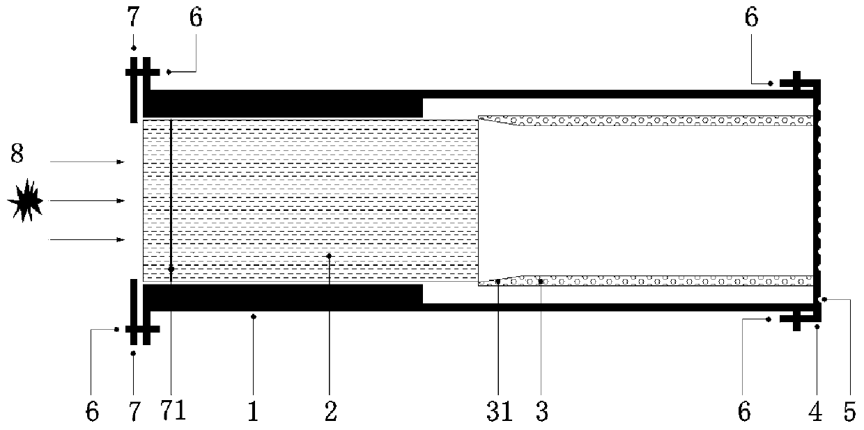
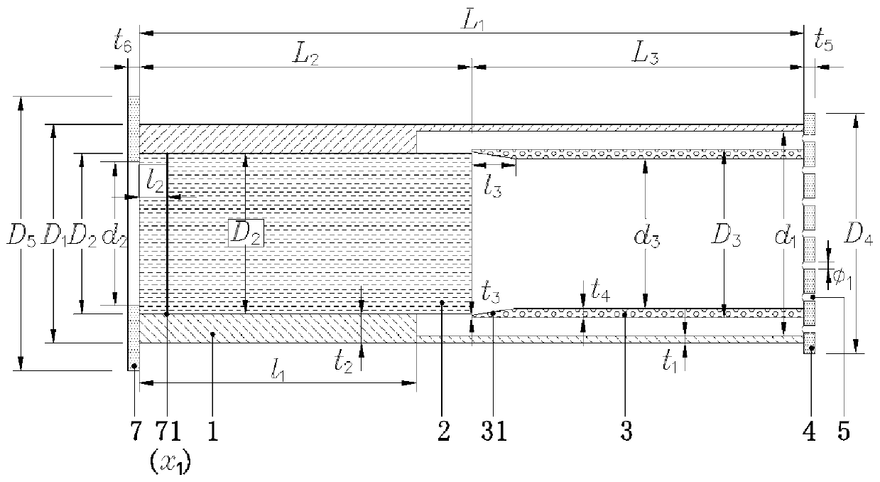
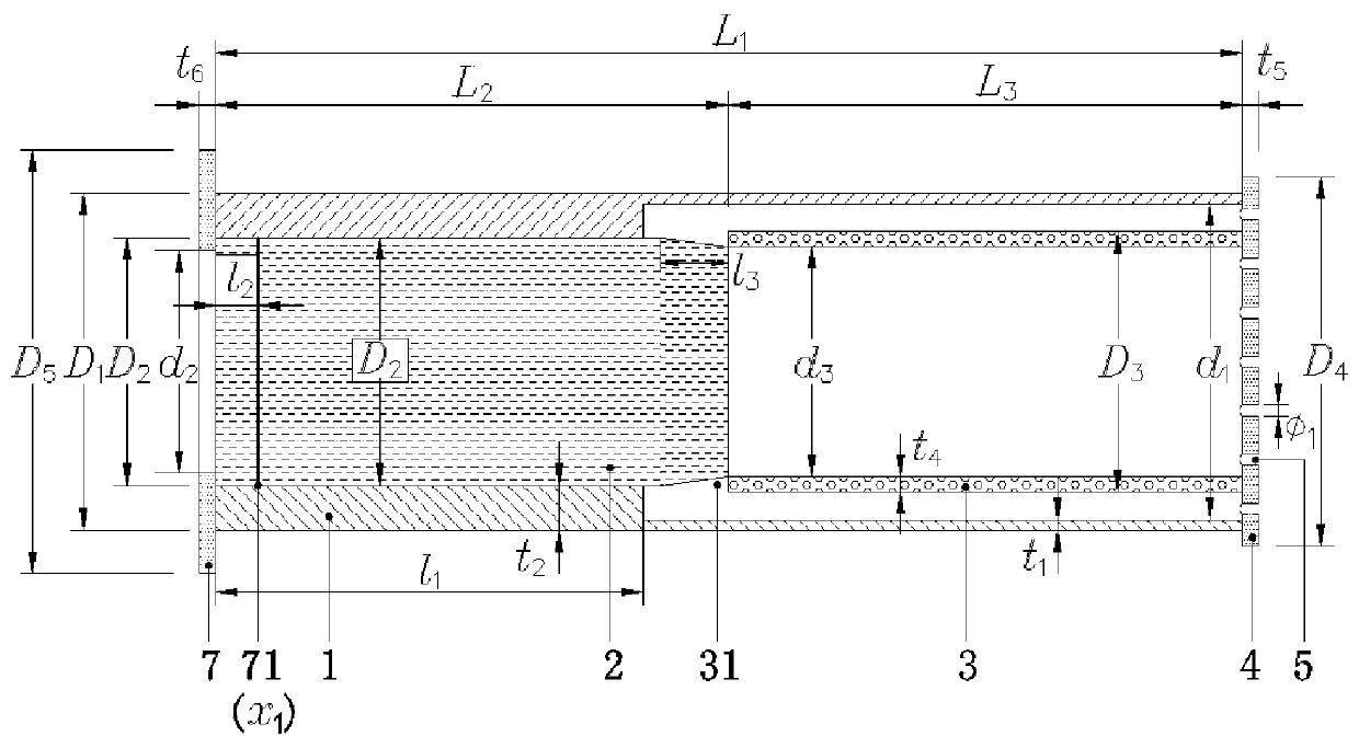
[0036] figure 1 It is a schematic diagram of the overall structure of the present invention. Such as figure 1 As shown, the present invention is composed of a package casing 1, a driving rod 2, a thin-walled tube energy-absorbing member 3, a solid-wall stop plate 4, a movable bolt 6, and a sealing retaining ring 7. Define the end of the present invention close to the explosion point 8 as the left end, and define the end of the present invention away from the explosion point 8 as the right end. The driving rod 2 and the thin-walled tube energy-absorbing member 3 are located in the encapsulation shell 1, the solid-wall stop plate 4 is fixed on the right end of the encapsulation shell 1 by movable bolts 6, and the right en...


PUM

PropertyMeasurementUnit
Yield strengthaaaaaaaaaa
Densityaaaaaaaaaa
Yield strengthaaaaaaaaaa

Abstract

The invention discloses a passive measurement shock wave energy sensor based on thin-walled tube expansion energy absorption, and aims to overcome the defects that an existing passive measurement method is complex in post-processing procedure, complex in measurement system and the like. The device consists of a packaging shell, a driving rod piece, a thin-walled tube energy absorption component, awall fixing stop plate, a movable bolt and a sealing baffle ring, wherein the driving rod piece, the thin-walled tube energy absorption component and the packaging shell are coaxially mounted. The driving rod piece does not generate plastic deformation under the action of explosion shock waves, and when the driving rod piece inserts the thin-walled tube energy absorption component under the action of the shock waves, the thin-walled tube energy absorption component deforms. Insertion displacement of the driving rod piece is measured, and passive quantitative measurement of shock wave energy is achieved by means of the relation between deformation displacement and absorbed energy. The sensor is simple in structure, free of power supply, convenient to arrange, low in cost and reusable, hashigh response sensitivity to shock waves with different intensities, and solves the technical problem that it is difficult to quantitatively test the energy of the shock waves in a severe environment.

Description

technical field [0001] The invention belongs to the field of measurement and detection, and in particular relates to a sensor for measuring shock wave parameters generated by an explosion, which is a passive sensor for measuring explosion shock wave energy by utilizing the elastic-plastic expansion deformation energy absorption characteristics of materials. Background technique [0002] The methods of measuring the pressure, impulse and other parameters of the shock wave generated by the explosion of explosives can generally be divided into two types: active measurement and passive measurement. Among them, active measurement mainly relies on various electrical sensors. Electrical sensor measurement technology is relatively mature and is the most popular testing method. There are various high-precision shock wave electrical measurement sensors on the market, but in some natural environments Under relatively harsh conditions, such as deserts, plateaus or islands, where the exp...

Claims


Application Information

Patent Timeline
IPC IPC(8): G01L5/00
CPCG01L5/0052
Inventor 林玉亮祁子真张玉武彭永梁民族李志斌陈荣李翔宇卢芳云
Owner NAT UNIV OF DEFENSE TECH
Learn More