Well backwashing valve and oil extraction tube column
A technology for backwashing wells and oil pumping strings, which is applied in the direction of flushing wellbore, production fluid, earthwork drilling and production, etc. It can solve the problem that the well flushing fluid cannot flush the inside of the oil well pump, and achieve the effect of improving oil production efficiency and rapid conversion
- Summary
- Abstract
- Description
- Claims
- Application Information
AI Technical Summary
Problems solved by technology
Method used
Image
Examples
Embodiment 1
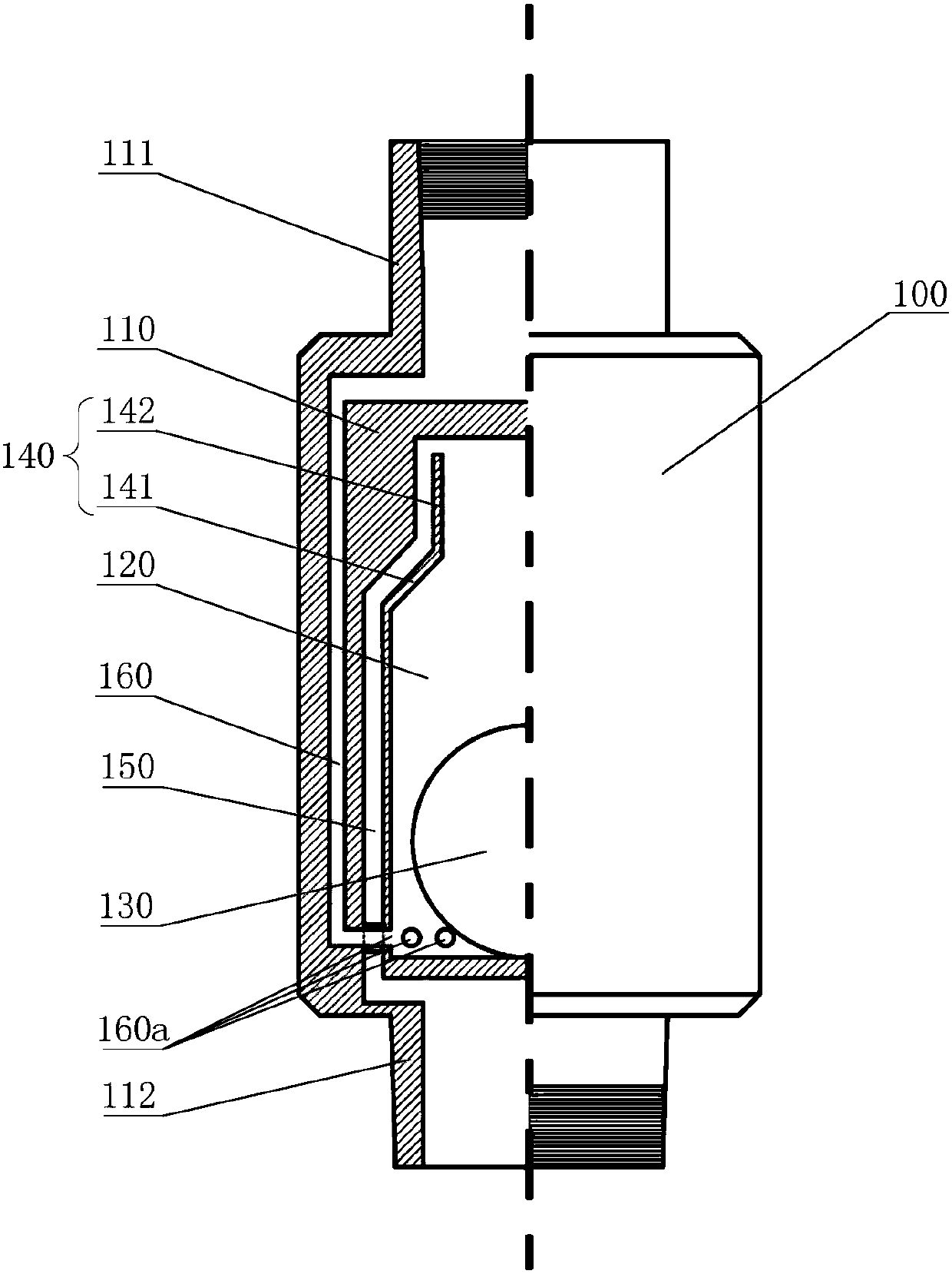
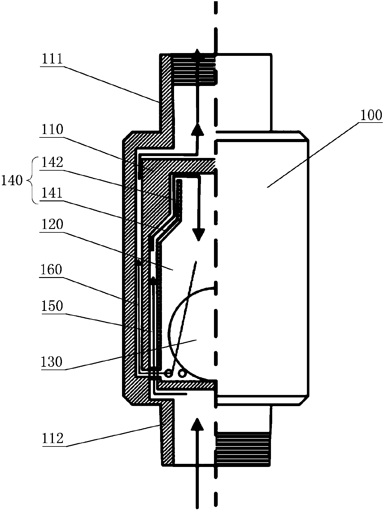
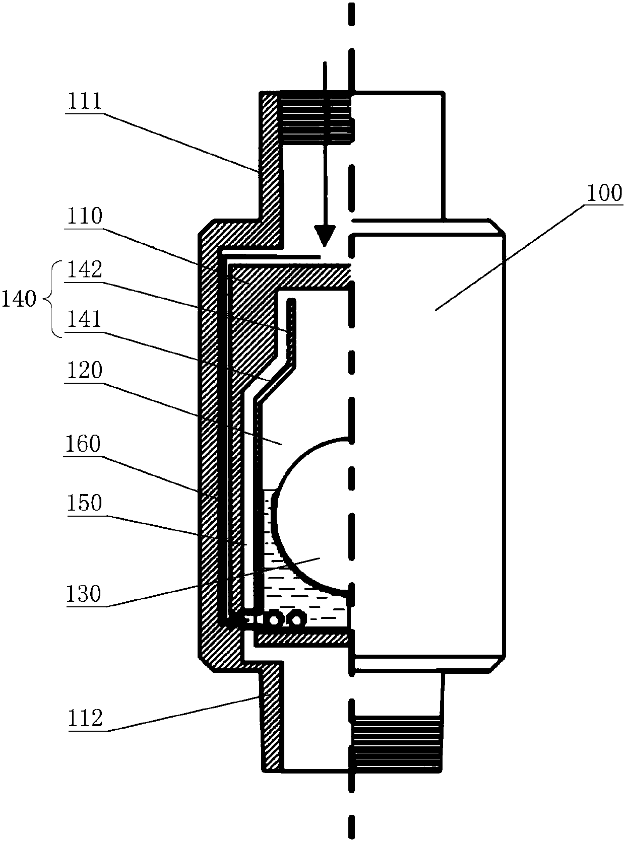
[0048] figure 1 A half-sectional schematic diagram of the structure of the backwash well valve provided in Embodiment 1 of the present invention. In this embodiment, a normal well flushing cycle cannot be established for carbonate reservoirs dominated by cave-type reservoirs. The flushing fluid injected back into the well usually leaks into the formation and cannot be reversed to the wellhead, so that the well flushing fluid cannot Flush the inside of the oil well pump, resulting in the problem of invalid flushing operation, provide a backwash valve 100, such as figure 1 As shown, the backwash well valve 100 of the present embodiment includes:
[0049] A housing 110, the top of the housing 110 is provided with an upper joint 111, and the bottom of the housing 110 is provided with a lower joint 112;
[0050] The inside of the housing 110 is formed with a float chamber 120, the float chamber 120 is provided with a float 130, and the float 130 can move up and down in the float ...
Embodiment 2
[0069] Figure 8 It is a schematic diagram of the backwash well valve 100 installed in the production string provided by Embodiment 2 of the present invention. In this embodiment, a normal well flushing cycle cannot be established for carbonate reservoirs dominated by cave-type reservoirs. The flushing fluid injected back into the well usually leaks into the formation and cannot be reversed to the wellhead, so that the well flushing fluid cannot Flush the inside of the oil well pump, resulting in the problem of ineffective flushing operation, provide a production string, such as Figure 8 As shown, the production tubing string in this embodiment includes the backwash well valve 100 described in Embodiment 1, and also includes an oil extraction tubing string 300 , a packer 200 and a lower tubing string 500 communicating with the packer 200 .
[0070] Wherein, the oil extraction string 300 is connected to the wellhead, and the oil extraction string 300 includes an oil well pump...
Embodiment 3
[0078] Figure 9 It is a schematic diagram of the backwash well valve 100 installed in the production string provided by the third embodiment of the present invention. In this embodiment, a normal well flushing cycle cannot be established for carbonate reservoirs dominated by cave-type reservoirs. The flushing fluid injected back into the well usually leaks into the formation and cannot be reversed to the wellhead, so that the well flushing fluid cannot Flush the inside of the oil well pump, resulting in the problem of ineffective flushing operation, provide a production string, such as Figure 9 As shown, the production string of this embodiment includes the backwash valve 100 described in Embodiment 1, and also includes a suction string 300, a perforated pipe 600, a packer 200, and a valve connected to the packer 200. Lower tubing string 500.
[0079] Wherein the oil extraction string 300 is connected to the wellhead, and the oil extraction string 300 includes an oil well ...
PUM
 Abstract
Description
Claims
Application Information
 - Generate Ideas
- Intellectual Property
- Life Sciences
- Materials
- Tech Scout
- Unparalleled Data Quality
- Higher Quality Content
- 60% Fewer Hallucinations
Browse by: Latest US Patents, China's latest patents, Technical Efficacy Thesaurus, Application Domain, Technology Topic, Popular Technical Reports.
© 2025 PatSnap. All rights reserved.Legal|Privacy policy|Modern Slavery Act Transparency Statement|Sitemap|About US| Contact US: help@patsnap.com


