
Pathological tissue dehydration instrument

A tissue and pathological technology, applied in the field of pathological tissue dehydration instrument, can solve the problems of slow dehydration process, inability to use continuous concentration dehydration, poor effect, etc., and achieve the effect of good effect, avoidance of errors and convenient operation.

Active Publication Date: 2020-04-03
李惠
View PDF17 Cites 0 Cited by
  • Summary
  • Abstract
  • Description
  • Claims
  • Application Information

AI Technical Summary

Problems solved by technology

However, the device cannot use continuous concentration dehydration, the dehydration process is slow, and the effect is not good.

Method used


Image

  • Pathological tissue dehydration instrument
  • Pathological tissue dehydration instrument
  • Pathological tissue dehydration instrument

Examples


Embodiment 1

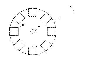
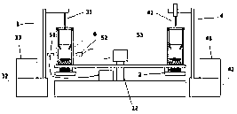
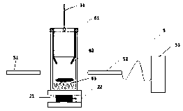
[0037] This embodiment describes the structure of the present invention. combine Figure 1-3 , a pathological tissue dehydration instrument, comprising a shell, a rotating tray 1, a stirring control chassis 2, a liquid injection control module 3, a liquid pumping control module 4, a concentration detection module 5, a dehydration cuvette 6, a main controller 7; a rotating tray 1. The stirring control chassis 2, the liquid injection control module 3, the liquid pumping control module 4, and the concentration detection module 5 are all connected to the main controller 7;

[0038] The rotating tray 1 is provided with a plurality of cuvette stations 11, and the dehydration cuvette 6 is detachably connected to the cuvette stations 11; the rotating tray 1 rotates horizontally under the drive of the rotating motor 12; multiple stirring control The chassis 2 is arranged on the lower side of the rotary tray 1, and corresponds to the position of the cuvette station 11, and the stirring...

Embodiment 2

[0053] This embodiment introduces the method of using the device.

[0054] Step 1. Weigh the mass m of the fixed sample to be dehydrated, and input the weighed mass m and the dehydration coefficient k corresponding to the type of the sample to be dehydrated into the main controller 7;

[0055] Step 2, the main controller 7 calculates the dehydration time t and the concentration endpoints c1 and c2 of the sample to be dehydrated according to m and k; wherein c1 is the lowest concentration value, and c2 is the highest concentration value;

[0056] Among them, t=kt0; t0 is the standard time interval, which is a fixed value, and k is the dehydration coefficient, which is a dimensionless constant, which is related to the difficulty of dehydration of the sample to be dehydrated and can be adjusted manually; c1 and c2 are the Two concentration constants related to the type of sample;

[0057] Step 3, the main controller 7 controls the rotating tray 1 to rotate, and drives an empty d...


PUM


Abstract

The invention relates to a pathological tissue dehydration instrument, which comprises a shell, a rotary tray, a stirring control chassis, a liquid injection control module, a liquid pumping control module, a concentration detection module, a dehydration cuvette and a main controller. The rotary tray, the stirring control chassis, the liquid injection control module, the liquid pumping control module and the concentration detection module are all connected with the main controller. A plurality of cuvette stations are arranged on the rotary tray, and the dehydration cuvettes are detachably connected to the cuvette stations. The liquid injection control module and the liquid pumping control module are arranged above the rotary tray, the liquid injection control module is provided with a liquid injection needle, the liquid pumping control module is provided with a liftable liquid pumping needle, and the position of the liquid injection control module or the liquid pumping control module corresponds to the position of the cuvette station. According to the invention, a plurality of dehydration devices are integrated in one independent device, and only sample taking and placing and arrangement of the controller are needed during dehydration, so that the operation is convenient, and the automation degree is high.

Description

technical field [0001] The invention relates to the technical field of medical detection instruments, in particular to a pathological tissue dehydration instrument. Background technique [0002] After the tissue is dehydrated with a series of alcohols, treated with a transparent agent, impregnated with melted paraffin, and embedded, the sections cut into sections are called paraffin sections. It is suitable for autopsy, clinical biopsy and some scientific research slices. [0003] The process of replacing the water contained in the tissue or cells with a dehydrating agent is called tissue dehydration. Both normal tissue and diseased tissue contain different levels of water. According to measurements, the material composition of the human body contains about 55-67% water, 15-18% protein, 10-15% lipid, 3-4% inorganic salt and 1-2% sugar. If this moisture is not removed, paraffin sectioning will not be possible. [0004] Application number: 01133294.8 discloses a living tis...

Claims


Application Information

Patent Timeline
IPC IPC(8): G01N1/28G01N21/3577
CPCG01N1/28G01N21/3577
Inventor 李惠鹿云香
Owner 李惠
Learn More