
A filter device for medical waste liquid

A filter device and waste liquid technology, applied in the field of medical equipment, can solve the problems of not being able to find the blockage of the filter in time

Active Publication Date: 2021-02-19
遵义市播州区人民医院
View PDF7 Cites 0 Cited by
  • Summary
  • Abstract
  • Description
  • Claims
  • Application Information

AI Technical Summary

Problems solved by technology

[0004] The present invention intends to provide a medical waste liquid filtering device to solve the problem that the filter sheet cannot be found to be blocked in time when the waste liquid is filtered in the prior art

Method used


Image

  • A filter device for medical waste liquid
  • A filter device for medical waste liquid

Examples


Embodiment Construction

[0018] Further detailed explanation through specific implementation mode below:

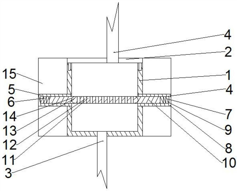
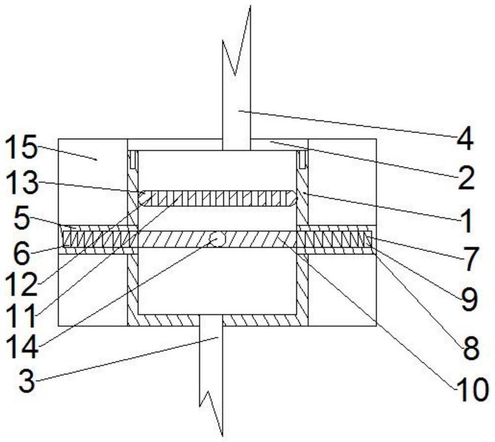
[0019] The reference signs in the drawings of the description include: filter box 1, box cover 2, liquid inlet pipe 3, liquid discharge pipe 4, first bump 5, first limit groove 6, spring 7, second bump 8, The second limiting groove 9 , the resisting block 10 , the filter plate 11 , the through hole 12 , the arc-shaped protrusion 13 , the locking groove 14 , and the sleeve 15 .

[0020] The embodiment is basically as attached figure 1 And attached figure 2 Shown:

[0021] A medical waste liquid filtering device, comprising a transparent rectangular filter box 1, a box cover 2 is provided on the filter box 1, a liquid inlet pipe 3 is connected to the bottom of the filter box 1, and a liquid discharge pipe is connected to the box cover 2 4. A first protrusion 5 is provided on the side wall of the filter box 1, and a first limiting groove 6 is arranged inside the first protrusion 5, and the first...


PUM


Abstract

This application discloses a medical waste liquid filtering device in the field of medical devices. The first limiting groove communicates with the filter box. The first limiting groove is provided with a first elastic member. The other side wall of the filter box is provided with a Two protrusions, the second protrusion is provided with a second limiting groove, the second limiting groove communicates with the filter box, the second limiting groove is provided with a second elastic member; the first elastic member and the second elastic member are Both are connected with a resisting block, a filter sheet is provided in the filter box, a number of through holes are provided on the filter sheet, and elastic protrusions are provided on the side wall of the filter sheet, and the elastic protrusions are in contact with the inner wall of the filter box and are in contact with the filter box. The inner walls of the two abutting blocks are slidingly connected; the side walls of the two abutting blocks are provided with slots matching the protrusions, and the filter is located between the two abutting blocks when the first elastic member and the second elastic member are compressed. By adopting the application, it is found that the filter sheet is blocked in time, and then the filter sheet can be replaced in time.

Description

technical field [0001] The invention belongs to the field of medical equipment, and in particular relates to a medical waste liquid filtering device. Background technique [0002] In the hospital, waste liquids such as sputum, blood and urine from patients are uniformly stored in plastic barrels, and there are waste liquid inlets and waste liquid discharge ports on the plastic barrels. When the waste liquid in the plastic barrels collects After it is full, the waste liquid needs to be treated; when processing, first connect the drain pipe to the waste liquid discharge port on the plastic barrel, and the drain pipe is provided with a filter device, which is connected with the suction device (used for suction operation). Hemorrhage, exudate and pus, etc.); then activate the suction device, which generates suction, and then sucks the waste liquid in the plastic bucket into the drain pipe, passes through the filter device and enters the suction device. [0003] The filter devic...

Claims


Application Information

Patent Timeline
Patent Type & Authority Patents(China)
IPC IPC(8): B01D29/03B01D35/30
CPCB01D29/03B01D35/30
Inventor 杨芳
Owner 遵义市播州区人民医院
Learn More