
Self-compacting concrete pouring method and pouring tool thereof

A self-compacting concrete and concrete technology, applied in construction, building structure, construction material processing and other directions, can solve the problems of concrete waste, hidden dangers to the personal safety of pouring personnel, etc., to reduce construction costs, improve safety, and expand the opening section. The effect of size

Inactive Publication Date: 2019-08-02
CHINA MCC20 GRP CORP +1
View PDF5 Cites 3 Cited by
  • Summary
  • Abstract
  • Description
  • Claims
  • Application Information

AI Technical Summary

Problems solved by technology

[0003] One of the purposes of the present invention is to provide a self-compacting concrete pouring method to solve the problems of a large amount of concrete waste and hidden dangers to the personal safety of pouring personnel in the existing process of pouring concrete into steel columns

Method used


Image

  • Self-compacting concrete pouring method and pouring tool thereof
  • Self-compacting concrete pouring method and pouring tool thereof

Examples


Embodiment 1

[0022] Embodiment 1: A method for pouring self-compacting concrete.

[0023] The invention provides a kind of pouring method of pouring concrete, and this pouring method comprises the following steps:

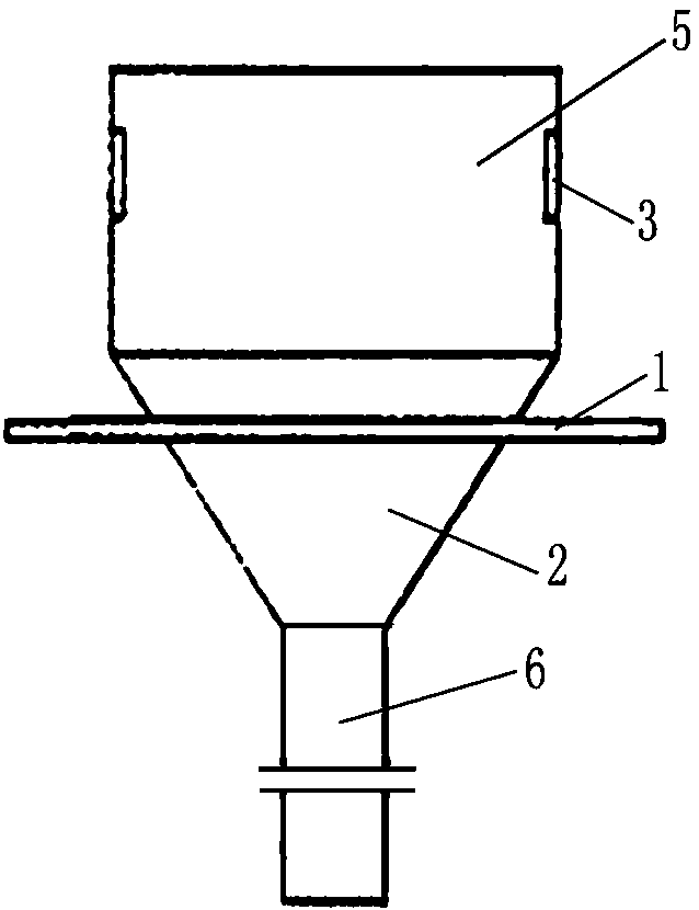
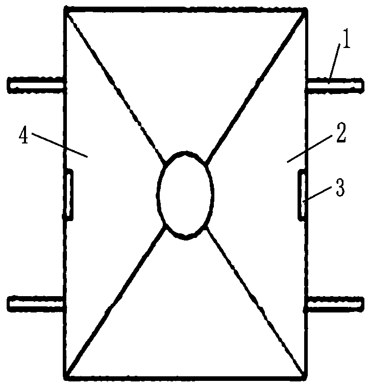
[0024] Firstly, a self-compacting pouring tool is prepared, and the self-compacting pouring tool includes a funnel and a support beam 1 arranged on the outer wall of the funnel. The funnel includes a rectangular cylinder 5 arranged at the upper end, an inclined cylinder 2 connected to the lower end of the rectangular cylinder 5 , and a guide cylinder 6 connected to the lower end of the rectangular cylinder 5 . The rectangular cylinder 5 is a hollow cylindrical body with a rectangular cross-section surrounded by four rectangular plates. The inclined cylinder 2 is surrounded by four inclined plates 4 corresponding to the rectangular plates. The rectangular plate shrinks obliquely from the connection end with the rectangular cylinder 5 to the middle of the funnel, and forms a rou...

Embodiment 2

[0030] Embodiment 2: A self-compacting concrete pouring tool.

[0031] like figure 1 , figure 2 As shown, the present invention provides a self-compacting concrete pouring tool, the structure of which includes a funnel and a support beam 1 arranged on the outer wall of the funnel. The funnel includes a rectangular cylinder 5 arranged at the upper end, an inclined cylinder 2 connected to the lower end of the rectangular cylinder 5 , and a guide cylinder 6 connected to the lower end of the rectangular cylinder 5 . The rectangular cylinder 5 is a hollow cylindrical body with a rectangular cross-section surrounded by four rectangular plates. The inclined cylinder 2 is surrounded by four inclined plates 4 corresponding to the rectangular plates. The rectangular plate shrinks obliquely from the connection end with the rectangular cylinder 5 to the middle of the funnel, and forms a round hole at the lower end. The contracted end It is in contact with the hollow cylindrical guide ...


PUM


Abstract

The invention provides a self-compacting concrete pouring method and a pouring tool thereof. The concrete pouring method comprises the following steps: a, a self-compacting concrete pouring tool is prepared; b, a truck crane is used for hoisting the self-compacting concrete pouring tool to the top of a steel column to be poured with concrete, the discharging port end of a funnel on the self-compacting concrete pouring tool penetrates into the steel column from the top of the steel column, and a supporting beam on the outer side wall of the funnel is supported on the top face of the steel column; c, a discharging pipe opening of a concrete conveying pipe connected with a cement pump truck or a concrete tank is aligned with a funnel on the pouring tool, flow concrete is injected into the funnel, and the flow concrete is injected into the steel column through a discharging opening of the funnel; and d, after pouring is completed, the truck crane is used for hoisting the pouring tool to the next steel column to be poured with concrete for pouring work. The concrete pouring device effectively solves the problems that in the process of pouring concrete into the steel column, it is difficult for concrete to be completely conveyed into the steel column, and potential safety hazards are generated to workers.

Description

technical field [0001] The invention relates to a concrete pouring method, in particular to a self-compacting concrete pouring method and a pouring tool thereof. Background technique [0002] During the construction of steel frame structures and grid structures, it is often necessary to pour concrete into circular steel columns and rectangular steel columns. When pouring concrete, it is necessary for the pouring personnel to stand on the top of the column and use the high throw method to pour. However, when using a pump truck or tower crane to pour cement into the steel column, the pump pipe will swing back and forth, and the opening cross-sectional size of the steel column is often small, making it impossible to ensure that the concrete enters the steel column effectively. Especially when the top of the steel column is already very high and the supporting structural floor slab has not been poured, it will not only easily lead to a lot of waste of concrete, but also the swi...

Claims


Application Information

Patent Timeline
Patent Type & Authority Applications(China)
IPC IPC(8): E04G21/02E04G21/04
CPCE04G21/02E04G21/04
Inventor 尚文龙马占国王刚修然
Owner CHINA MCC20 GRP CORP
Learn More