
Hydraulic lifting clamping jaw

A technology of hydraulic lifting and gripping claws, which is applied in the direction of trolley cranes, load hanging components, cranes, etc., can solve the problems of poor safety, low efficiency, and gripping claws that cannot meet the gripping requirements, and achieve the effect of strong gripping ability

Pending Publication Date: 2019-08-02
ZHEJIANG MILITARY IND GRP CO LTD
View PDF0 Cites 0 Cited by
  • Summary
  • Abstract
  • Description
  • Claims
  • Application Information

AI Technical Summary

Problems solved by technology

[0002] In the process of production and processing, it is often necessary to transport some heavy workpieces between different steps, especially for heavy castings, which are heavy in weight and high in temperature, and the use of forklifts and other transport vehicles also requires the workpiece to be lifted. Unloading also requires the use of tools such as driving, and the need to manually operate the forklift, which is inefficient and poor in safety. Therefore, for heavy castings, most of the heavy castings are remotely controlled to lift the jaws for transportation.
Existing gripper tools can only grip workpieces of similar size. If there are many types of workpieces produced, the grippers cannot meet the gripping of some particularly large or small workpieces. The medium is not stable enough, and it is easy to shake and affect the accuracy of workpiece unloading, so it is urgent to design a safe, stable and strong lifting jaw

Method used


Image

  • Hydraulic lifting clamping jaw
  • Hydraulic lifting clamping jaw

Examples


Embodiment Construction

[0030] The present invention will be further described through specific embodiments below in conjunction with the accompanying drawings.

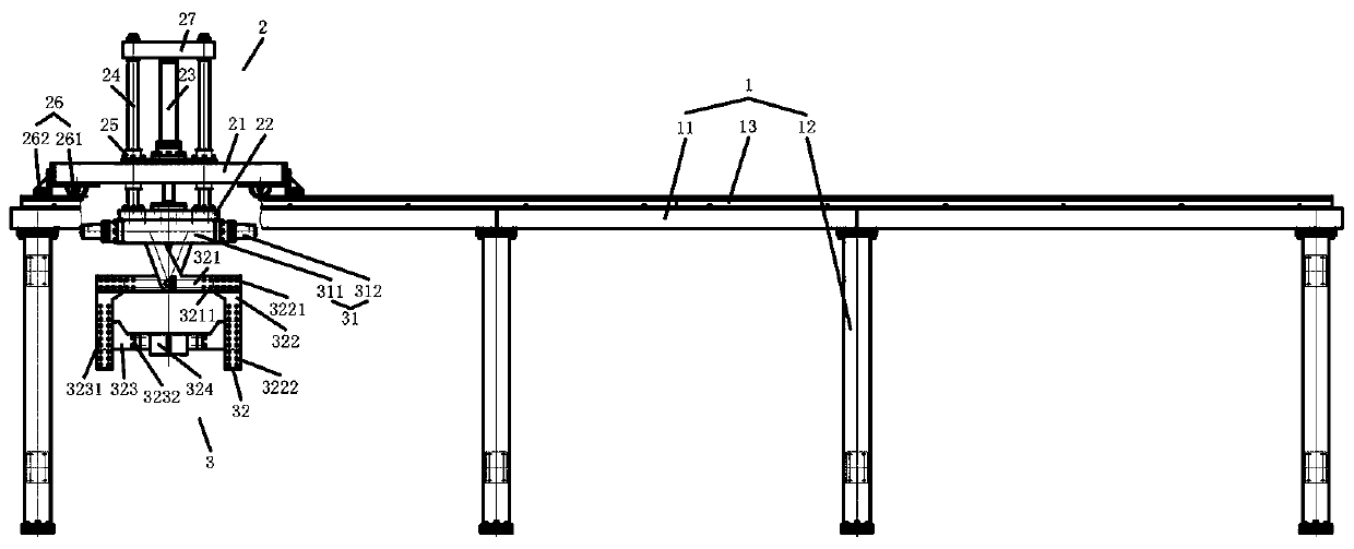
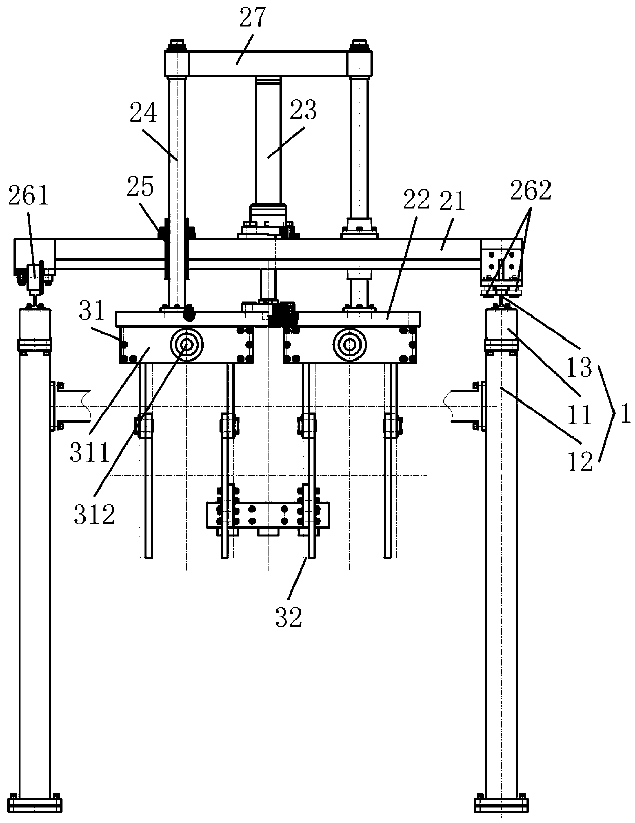
[0031] like figure 1 , figure 2 , a hydraulic lifting jaw, comprising:

[0032] The support frame 1, the support frame 1 includes two horizontally arranged and parallel translation support rods 11, a support leg 12 installed below the translation support rods 11 and a guide rail 13 installed above the translation support rods 11;

[0033] Move the lifting frame 2, the moving lifting frame 2 includes a horizontal support 21 installed on the guide rail 13, a lifting connection seat 22 located below the horizontal support 21, and a vertically installed on the horizontal support 21, and the piston rod end and the center position of the lifting connection seat 22 The connected lifting cylinder 23 is vertically connected to the guide rod 24 around the lifting connection seat 22 and passes through the horizontal support 21;

[0034] Gripper me...


PUM


Abstract

A hydraulic lifting clamping jaw comprises a supporting frame, a movable lifting frame and a clamping jaw mechanism. The supporting frame comprises two horizontally-arranged parallel translation supporting rods, supporting legs arranged below the translation supporting rods and guide rails arranged above the translation supporting rods. The movable lifting frame comprises a horizontal support arranged on the guide rails, a lifting connecting base arranged below the horizontal support, a lifting oil cylinder vertically arranged on the horizontal support and connected with the center of the lifting connecting base at the piston rod end, and a guide rod vertically connected to the top of the periphery of the lifting connecting base and penetrating through the horizontal support. The clampingjaw mechanism comprises a clamping jaw driving mechanism connected to the bottom of the lifting connecting base and a clamping jaw assembly connected to the bottom of the clamping jaw driving mechanism, and the clamping jaw assembly has an opening and closing clamping action under the effect of the clamping jaw driving mechanism.

Description

technical field [0001] The invention relates to the field of lifting and transporting heavy workpieces, and more specifically relates to a hydraulic lifting clamp. Background technique [0002] In the process of production and processing, it is often necessary to transport some heavy workpieces between different steps, especially for heavy castings, which are heavy in weight and high in temperature, and the use of forklifts and other transport vehicles also requires the workpiece to be lifted. Unloading also requires the use of tools such as driving and manual operation of forklifts, which is inefficient and poor in safety. Therefore, most heavy castings are transported by remote control of lifting jaws. Existing gripper tools can only grip workpieces of similar size. If there are many types of workpieces produced, the grippers cannot meet the gripping of some particularly large or small workpieces. The middle is not stable enough, and it is easy to shake and affect the acc...

Claims


Application Information

Patent Timeline
Patent Type & Authority Applications(China)
IPC IPC(8): B66C19/00B66C1/44B66C13/20
CPCB66C19/00B66C1/447B66C13/20
Inventor 姜舟罗金明刘宏符涛黄建国王云伟
Owner ZHEJIANG MILITARY IND GRP CO LTD
Learn More