
A High Speed ​​Switched Reluctance Generator Converter System

A reluctance generator and high-speed switching technology, which is applied to control the direction of the generator through the change of the magnetic field, can solve the problems of switching loss, narrow range, mechanical power instability, etc., and achieve improved power generation output, direct excitation, and fast response Effect

Active Publication Date: 2020-09-11
CHINA JILIANG UNIV
View PDF9 Cites 0 Cited by
  • Summary
  • Abstract
  • Description
  • Claims
  • Application Information

AI Technical Summary

Problems solved by technology

[0006] At present, internationally, the switched reluctance motor research group of the University of Podgorica in the Republic of Montenegro has realized the full-time continuous operation mode of the winding current of each phase when the switched reluctance generator is running, but most of the current conversion systems are not very good. Supporting this method, for example, requires a large number of switching tubes to operate in PWM mode, resulting in a large number of switching losses
[0007] Considering that the input mechanical power is unstable or the load changes, it is often necessary to automatically adjust the output electric energy or improve the electric energy output capacity according to changes in these surrounding conditions. The adjustability of the excitation power supply is an important and convenient operation regulation mode. However, most current variable excitation converter systems have a limited range of change, and rarely have a ratio of the highest to the lowest greater than 3. The range is narrow, which limits the greater flexibility and adaptability of the converter system.

Method used


Image

  • A High Speed ​​Switched Reluctance Generator Converter System

Examples


Embodiment Construction

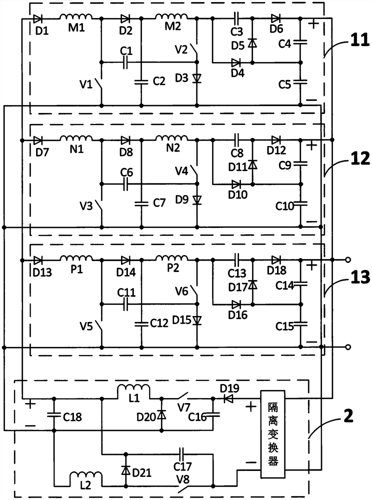
[0026] A high-speed switched reluctance generator converter system of this embodiment, as shown in the appendix figure 1 As shown, it consists of a first diode D1, a second diode D2, a third diode D3, a fourth diode D4, a fifth diode D5, a sixth diode D6, a seventh diode Diode D7, eighth diode D8, ninth diode D9, tenth diode D10, eleventh diode D11, twelfth diode D12, thirteenth diode D13, Fourteenth diode D14, fifteenth diode D15, sixteenth diode D16, seventeenth diode D17, eighteenth diode D18, nineteenth diode D19, twentieth diode The diode D20, the twenty-first diode D21, the first phase winding M1, the first phase winding two windings M2, the first switch tube V1, the second switch tube V2, the third switch tube V3, the fourth switch tube Switch tube V4, fifth switch tube V5, sixth switch tube V6, seventh switch tube V7, eighth switch tube V8, first capacitor C1, second capacitor C2, third capacitor C3, fourth capacitor C4, fifth Capacitor C5, sixth capacitor C6, sevent...


PUM


Abstract

Disclosed is a high-speed switch reluctance generator current conversion system; the high-speed switch reluctance generator current conversion system comprises three-phase-winding current conversion circuits of the same structure, and a variable excitation current conversion circuit, wherein the three-phase-winding current conversion circuits consist of three-phase of windings, eighteen diodes, fifteen capacitors and six switch tubes; the current conversion circuits of each phases of windings are the same in structure and are connected in parallel, so that high expandability is achieved; the structure and the control method of the variable excitation current conversion circuit under the self-excitation mode are as follows: the excitation voltage can be adjusted according to needs in a widerange; the current conversion circuits of each phases of windings are connected in parallel to obtain high voltage directly, so that a part of the current conversion links can be omitted; due to thefact that the current conversion circuit switch tube of each phase of winding works in a single-pulse-wave mode, so that the switch loss is low; meanwhile, a newest continuous operation mode can be supported and realized; the excitation voltage is independently obtained by splitting each phase of winding, so that the excitation capacity is improved; and the full-system control method is simple andsuitable for various fields of the current high-speed switch reluctance generators.

Description

technical field [0001] The invention relates to the field of switched reluctance generator systems, in particular to a converter of a high-speed switched reluctance generator and a control method thereof. Background technique [0002] The switched reluctance motor has a simple structure, low cost, no winding on the rotor, and low heat dissipation pressure. As a generator, it has considerable application value. [0003] At present, the more mature switched reluctance generator systems in commercial application are mostly high-speed operation. [0004] In many fields where switched reluctance generators are applied, a voltage much higher than the voltage output by direct power generation is often required, and a circuit to increase the voltage needs to be added to complete. If the high voltage is directly obtained, the traditional method Naturally, the different-phase winding power generation circuits are connected in series after output, but due to the time-sharing character...

Claims


Application Information

Patent Timeline
Patent Type & Authority Patents(China)
IPC IPC(8): H02P9/30
CPCH02P9/30
Inventor 孙冠群
Owner CHINA JILIANG UNIV
Learn More