
Direct-current microgrid power optimization configuration and operation method based on wave power generation

A technology of DC micro-grid and wave power generation, which is applied in parallel operation of DC power supplies, battery circuit devices, electromechanical devices, etc., and can solve problems such as easy to fall into local optimum, slow convergence speed, frequent switching of control strategies, etc.

Pending Publication Date: 2019-07-30
GUANGDONG UNIV OF TECH
View PDF8 Cites 8 Cited by
  • Summary
  • Abstract
  • Description
  • Claims
  • Application Information

AI Technical Summary

Problems solved by technology

[0003] The current control method of DC microgrid system for wave power generation mainly adopts voltage layered control, but this kind of control method scheme will cause frequent switching of control strategies due to bus voltage fluctuations.
[0004] For the power control of DC micro-grid systems with wave power generation, swarm intelligence optimization algorithms have been widely used in MPPT (Maximum Power Point Tracking, MPPT) in the fields of photovoltaic power generation and wind power generation. When solving complex optimization problems, its convergence speed is slow and it is easy to fall into local optimum, which limits the improvement of power control performance of wave power DC microgrid system

Method used


Image

  • Direct-current microgrid power optimization configuration and operation method based on wave power generation
  • Direct-current microgrid power optimization configuration and operation method based on wave power generation
  • Direct-current microgrid power optimization configuration and operation method based on wave power generation

Examples


Embodiment Construction

[0088] The present invention will be further described below in conjunction with specific embodiment:

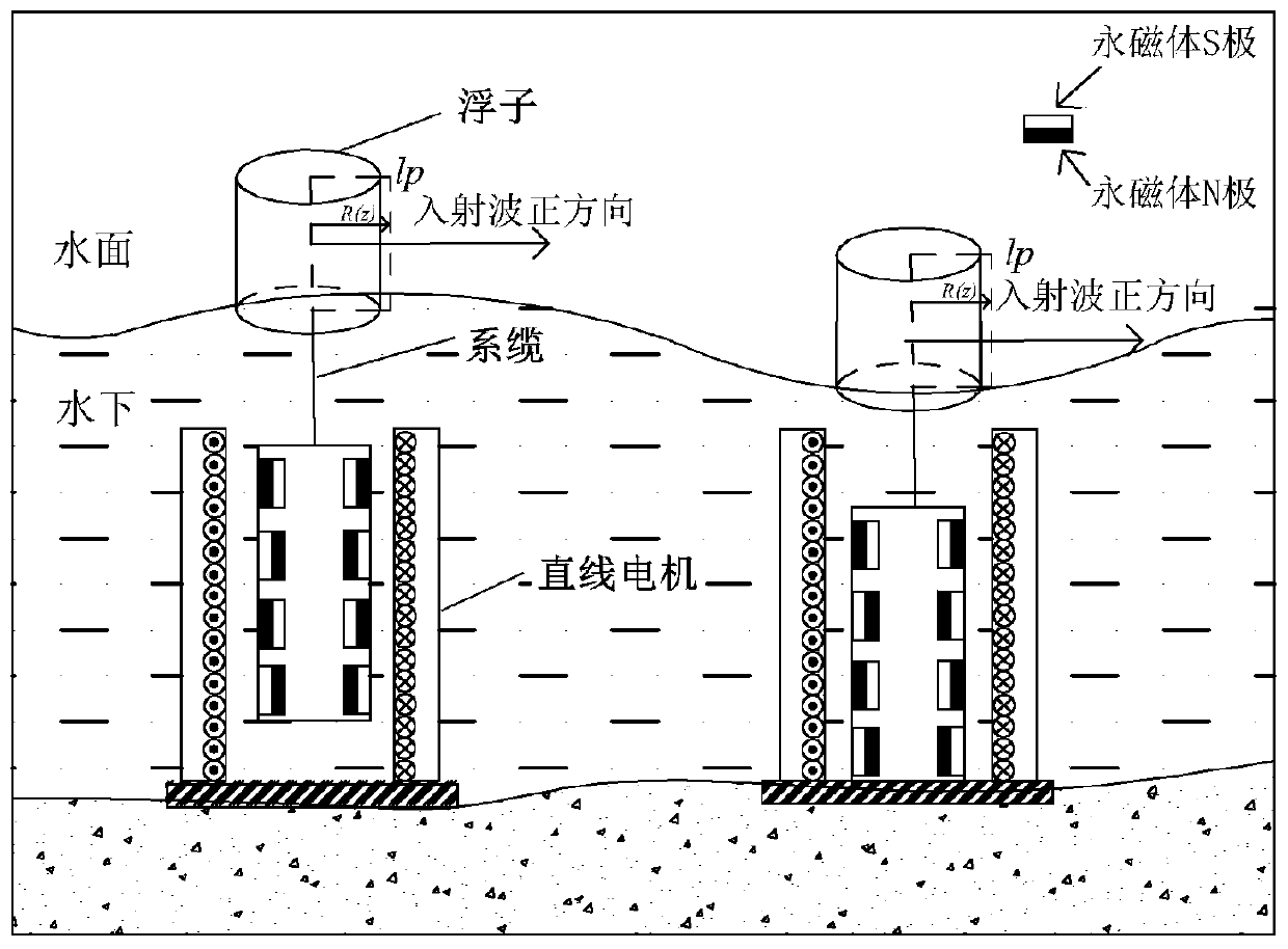
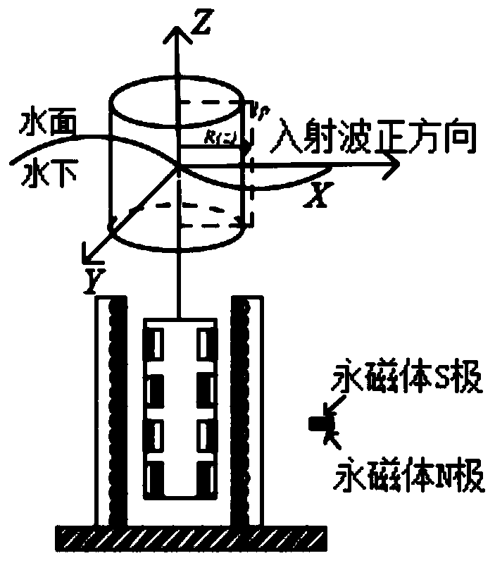
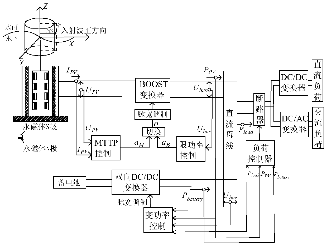
[0089] This embodiment is based on the wave power generation DC microgrid system, and its topological structure diagram is as follows image 3 As shown, the system consists of wave power generation device, storage battery, converter, control system, DC bus and load. Among them, I PV , U PV Output current and voltage for the wave power generation device; U bus is the DC bus voltage of the microgrid; P PV is the output power of the wave power generation device; P battery is the battery output power; P load is the load power; a M 、a B are the duty cycle of the Boost circuit output by the MPPT control module and the power limiting module respectively; a is the actual duty cycle of the Boost circuit of the wave power generation DC microgrid system, and when the wave power generation DC microgrid system adopts MPPT control, a=a M , when the wave power generation DC microgr...


PUM


Abstract

The invention discloses a direct-current microgrid power optimization configuration and operation method based on wave power generation. A storage battery adopts variable power control for dividing aworking state of a wave power generation direct-current microgrid system into multiple working states, and based on a power difference of the wave power generation capacity and the load consumption, the directions and values of charging and discharging power in the storage battery are controlled, so that the wave power generation direct-current microgrid system is switched in the multiple states.The power optimization of the wave power generation direct-current microgrid system is divided into MPPT control and limited power control: when the wave power generation direct-current microgrid system works in the MPPT control, the wave power generation direct-current microgrid system tracks a maximum output power point of a wave power generation device in combination with a criss-cross algorithm; and when the wave power generation direct-current microgrid system is in the limited power control, the wave power generation direct-current microgrid system is used for controlling output power ofthe wave power generation device in combination with the criss-cross algorithm. According to the method, the output power can maintain stable operation of the wave power generation direct-current microgrid system.

Description

technical field [0001] The invention relates to the technical field of power control of wave power generation devices, in particular to a method for optimal configuration and operation of DC micro-grid power based on wave power generation. Background technique [0002] With the rapid development of my country's island construction, the island's demand for energy continues to increase. Wave energy is a clean and renewable energy with great potential. Data show that rational development and utilization of wave energy can meet about 10% of the world's current total electricity demand, which is equivalent to the total actual power generation of large hydropower stations around the world. [0003] The current control method of DC microgrid system for wave power generation mainly adopts voltage layered control, but this kind of control method scheme will cause frequent switching of control strategies due to bus voltage fluctuations. [0004] For the power control of DC micro-grid...

Claims


Application Information

Patent Timeline
Patent Type & Authority Applications(China)
IPC IPC(8): H02J1/10H02J7/34F03B13/14H02K7/18
CPCH02J1/10H02J7/34F03B13/14H02K7/1876Y02E10/30
Inventor 谭绮仪
Owner GUANGDONG UNIV OF TECH
Learn More