An Axial Diaphragm Coupling

A diaphragm coupling and diaphragm technology, applied in the direction of couplings, elastic couplings, mechanical equipment, etc., can solve the problem that the angular displacement of compensation cannot meet the needs, the structure is not very reasonable, the main and driven shafts Problems such as synchronous bearing vulnerable

Active Publication Date: 2021-05-25
LUDONG UNIVERSITY
View PDF5 Cites 0 Cited by
  • Summary
  • Abstract
  • Description
  • Claims
  • Application Information

AI Technical Summary

Problems solved by technology

However, in order to ensure the synchronization of the main and driven shafts, the universal joints are in the form of duplexes in practical applications, and the bearings are the vulnerable parts of the universal joints.
Due to the unreasonable structure of the existing diaphragm coupling, the angular displacement that can be compensated sometimes cannot meet the needs; although the universal coupling has strong angular displacement compensation ability, there is synchronization between the main and driven shafts and bearings are vulnerable, so in order to solve the problems of diaphragm couplings and universal couplings, it is necessary to invent a diaphragm coupling with a more reasonable structure

Method used


Image

  • An Axial Diaphragm Coupling
  • An Axial Diaphragm Coupling
  • An Axial Diaphragm Coupling

Examples


Embodiment 1

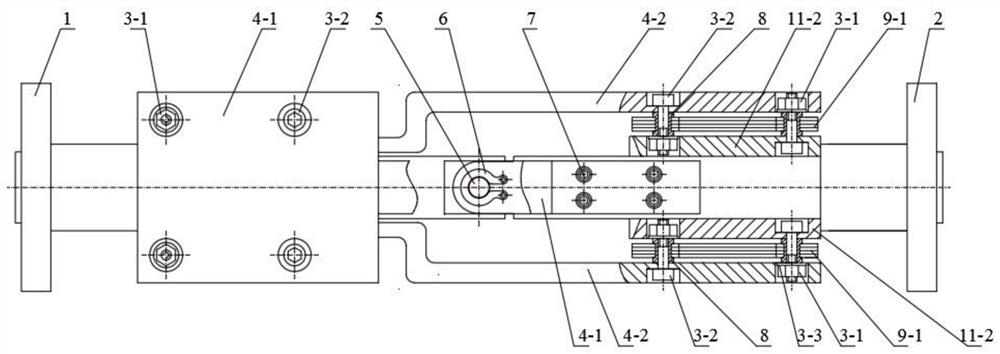
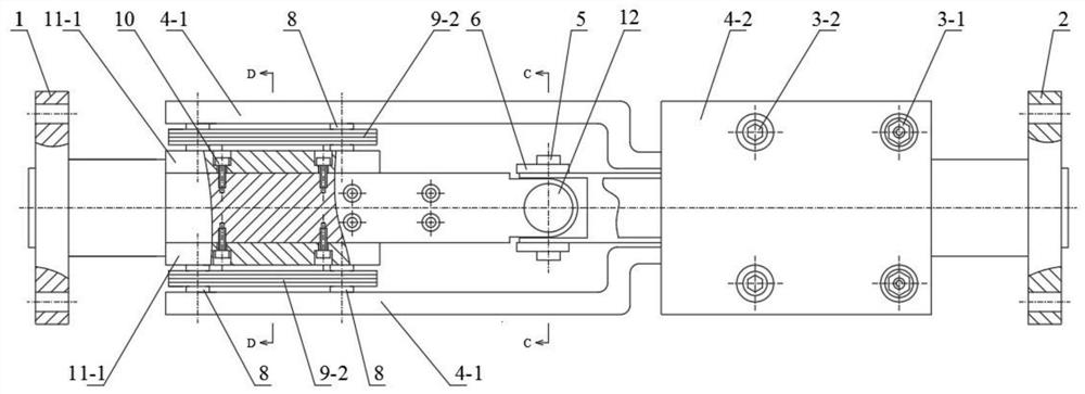
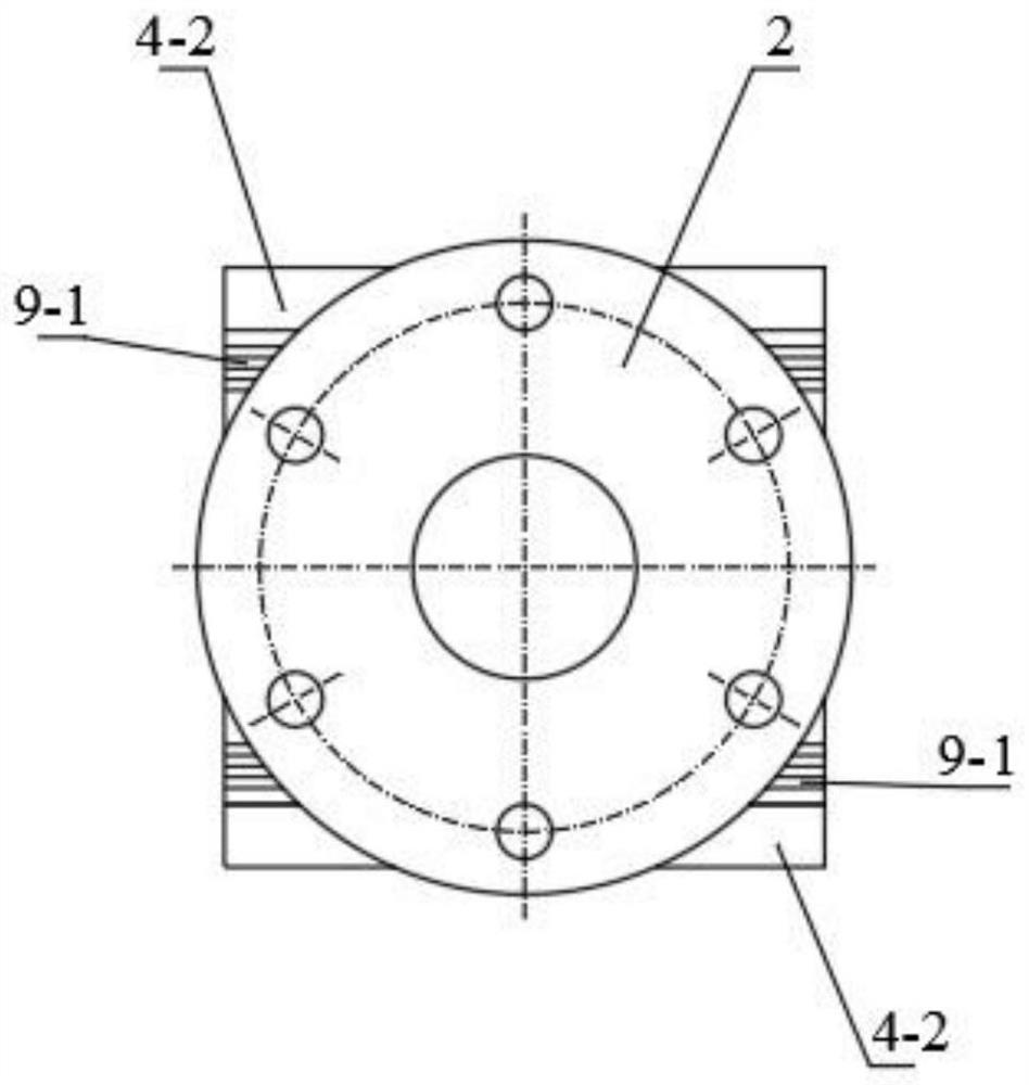
[0030] Embodiment 1, reference figure 1 , figure 2 , image 3 , Figure 4 , Figure 5 , Figure 6 , Figure 7 , Figure 8 , Figure 9 , Figure 10 , Figure 11 , Figure 12 , Figure 13 , Figure 14 , Figure 15 , Figure 16 , Figure 17 , Figure 18 , Figure 19 , Figure 20 , Figure 21 , Figure 22 , Figure 23 , Figure 24 . It can be seen from the accompanying drawings that an axial diaphragm coupling is composed of the first half-shaft section 1, the second half-shaft section 2, the diaphragm group connecting bolts and nuts 3-1, and the diaphragm group connecting bolts 3-2 , Diaphragm group connection bolt gasket 3-3, first diaphragm connection plate 4-1, second diaphragm connection plate 4-2, thin universal pin 5, thin universal pin spring retaining ring 6, diaphragm connection Plate fixing screw 7, diaphragm group fixing sleeve 8, first diaphragm group 9-1, second diaphragm group 9-2, diaphragm group fixing plate fixing screw 10, first diaphrag...


PUM


Abstract

The invention discloses an axial membrane coupling. Due to the existence of universal couplings in the existing structure, in order to ensure the synchronization of the main and driven shafts, the practical application of universal couplings generally adopts a duplex form, and the bearing is a wearing part of the universal coupling, etc. Problem: Because the diaphragm coupling of the existing structure cannot adapt to large angular displacement and other problems, it directly affects the performance and service life of the coupling. In order to solve these problems, a new type of diaphragm coupling in which the diaphragm group is arranged along the axial direction of the coupling is designed. The axial diaphragm coupling of this structure has the unique working performance of diaphragm coupling and universal coupling, which can not only compensate for large angular displacement, but also ensure the synchronization of the main and driven shafts. Improve the bearing capacity and service life of the coupling.

Description

technical field [0001] The invention relates to a coupling of a mechanical transmission device, which is a coupling device for movement and power transmission between a prime mover (such as an electric motor, an internal combustion engine, etc.) and a working machine (such as a pump, a reducer, etc.), and belongs to the technical field of mechanical transmission . Background technique [0002] Couplings are widely used in rotating machinery, including rigid couplings and elastic couplings. Diaphragm coupling is a new type of coupling, which has the advantages of transmitting large torque, allowing large displacement error, allowing high-speed rotation, mitigating impact vibration, generally does not need lubrication, and is easy to install and maintain. It is widely used in National defense, shipbuilding, aviation, petrochemical, vehicles, machinery and other industries can replace gear couplings, elastic sleeve pin couplings and other coupling devices. The universal coupl...

Claims


Application Information

Patent Timeline
Patent Type & Authority Patents(China)
IPC IPC(8): F16D3/26F16D3/10
CPCF16D3/10F16D3/26
Inventor 王亮申陈燕王昕彦田忠民王晓晨
Owner LUDONG UNIVERSITY
Why Eureka
Try Eureka