Drive device for detaching rollers of a comber

A technology for driving equipment and separating rollers, applied in combing machines, textiles and papermaking, fiber processing, etc., can solve problems such as large unevenness, fiber tip folding, etc.

Active Publication Date: 2019-07-30
MASCHINENFABRIK RIETER AG
View PDF5 Cites 0 Cited by
  • Summary
  • Abstract
  • Description
  • Claims
  • Application Information

AI Technical Summary

Problems solved by technology

[0005] A disadvantage with respect to yarn quality is that the fiber tips are folded due to the adjustment of the control cam on known combers
However, this leads to large inhomogeneities (CV values) measured on the strips, but this result correlates to a yarn quality that cannot be recommended for further use

Method used


Image

  • Drive device for detaching rollers of a comber
  • Drive device for detaching rollers of a comber
  • Drive device for detaching rollers of a comber

Examples


Embodiment Construction

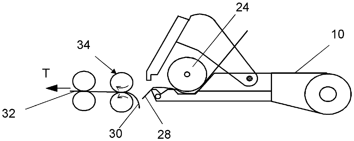
[0033] figure 1 A cross-section through the combing station 2 on the combing machine 4 is schematically shown. In practice, eight such combing stations 2 are arranged side by side. Each combing station 2 is made up of a nipper assembly 10 (referred to as nipper for short), and this nipper 10 executes the forward and backward movement of the nipper 10 by means of a front rocker 12 and a rear rocker 14 . Front rockers 12 (only one shown) are mounted in a rotationally movable manner on a circular comb shaft 16 and on a front nipper hub 18 of the nipper 10 . A rear rocker 14 mounted on a rear nipper axle 20 of the nipper 10 so that it can move rotationally is connected in a rotationally fixed manner to a driven nipper shaft 22 . The cotton filling 26 is fed to a feeding cylinder 24 installed inside the nipper 10 such that the cotton filling 26 can be rotationally moved. The filler material 26 is unwound from a folded roll (not shown) which rests on take-up rolls (also not shown...


PUM

PropertyMeasurementUnit
diameteraaaaaaaaaa
diameteraaaaaaaaaa

Abstract

The invention relates to a drive device for a separating roller (34) of a comber (4), the drive device having a housing (60a) surrounding a gear device (51a). The gear device (51a) has a first drive train (62) of a drive shaft (64), the first drive shaft (64) transmits a continuous rotational motion to the separating roller (34) via a hollow wheel (74) of a differential gear device (66), and the gear unit (51a) has a second drive train (68) with a separation roller auxiliary shaft (70), and the separation roller cam disc device (72) is disposed on the separation roller auxiliary shaft (70) togenerate forward and backward movement. Through the continuous rotational movement of the hollow wheel (74) and the forward and backward movement of the separation cam disc device (72), the reciprocating motion is transmitted to a separating roller. According to the invention, an adjustment mechanism (158) is provided for adjusting the gear ratio between the continuous rational motion and the forward and backward movement.

Description

technical field [0001] The invention relates to a drive device for a detaching roller of a combing machine, the drive device having a housing surrounding a gear unit, wherein the gear unit has a first drive train with a first drive shaft via a differential a high-speed gearing transfers the continuous rotary motion to the separation roller, and wherein the gearing has a second drive train with a separation roller auxiliary shaft on which the separation roller cam disc arrangement is arranged for generating the forward and backward movement, The continuous rotational movement of the differential gear unit, together with the back-and-forth movement of the separation roller cam plate arrangement, transmits the reciprocating motion to the separation roller. Background technique [0002] In a comber with several combing stations, for each nipper assembly, fiber bundles of cotton wadding are presented to be combed out to circular combs arranged below the nipper assembly, which Th...

Claims


Application Information

Patent Timeline
Patent Type & Authority Applications(China)
IPC IPC(8): D01G19/26D01G19/18
CPCD01G19/26D01G19/18
Inventor H.韦伯D.波梅
Owner MASCHINENFABRIK RIETER AG
Why Eureka
Try Eureka