Eureka AIR delivers breakthrough ideas for toughest innovation challenges, trusted by R&D personnel around the world.

High-power converter including low-power transistors connected in parallel

一种晶体管、并联的技术,应用在输出功率的转换装置、交流功率输入变换为直流功率输出、电气元件等方向,能够解决电流不平衡、开关破坏等问题

Active Publication Date: 2019-07-26
GE ENERGY POWER CONVERSION TECH
View PDF5 Cites 0 Cited by
  • Summary
  • Abstract
  • Description
  • Claims
  • Application Information

AI Technical Summary

Problems solved by technology

This then leads to a current imbalance between the two switches, especially during the commutation phase of the switches, which in some cases leads to the destruction of one of the two switches

Method used


Image

  • High-power converter including low-power transistors connected in parallel
  • High-power converter including low-power transistors connected in parallel
  • High-power converter including low-power transistors connected in parallel

Examples


Embodiment Construction

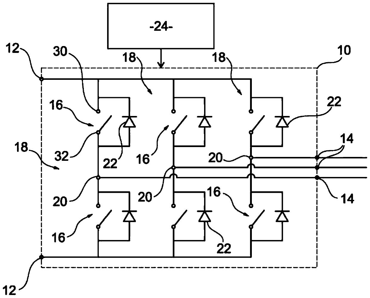
[0023] The invention relates to a system 10 for converting a first voltage into a second voltage comprising at least two input terminals 12 and at least two output terminals 14 . The conversion system 10 comprises a commutation component 16 arranged between the input terminal 12 and the output terminal 14 and adapted to convert a first voltage into a second voltage.

[0024] The conversion system is suitable to allow high electrical power (eg greater than 1 MW) to be cycled.

[0025] exist figure 1 In an embodiment of the present invention, the conversion system 10 is a voltage inverter adapted to convert a continuous DC input voltage received between two input terminals 12 into an AC output voltage delivered at each of the output terminals 14 .

[0026] The voltage inverter 10 comprises two commutation paths 18 for each phase of the AC output voltage, each commutation path 18 being connected between a corresponding output terminal 14 and a corresponding input terminal 12 and...


PUM


Abstract

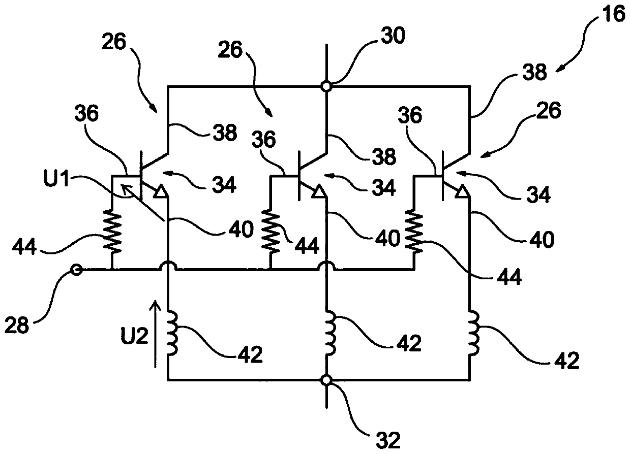
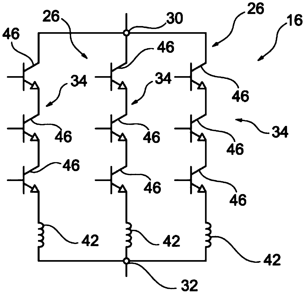
The invention relates to a system for converting a first electric voltage into a second electric voltage, comprising: at least two input terminals and two output terminals; and switching members (16)disposed between the input and output terminals, which can convert the first voltage into the second voltage. At least one switching member (16) comprises at least two arms (26) connected in paralleland each arm includes an electronic switch (34) that can be controlled such as to occupy either an on-state or an off-state, said switch comprising a control electrode (36) and two conduction electrodes (38, 40) that conduct current in the on-state. The switching member (16) comprises a common control terminal (28) connected to the control electrode (36) of the switch of each arm, as well as a first common conduction terminal (30) and a second common conduction terminal (32) connected respectively to a first conduction electrode (38) and a second conduction electrode (40) of the switch (34) ofeach of the arms. The switching member (16) also comprises, for each arm, an inductance (42) connected between the same single electrode from the two conduction electrodes (38, 40) and the corresponding common conduction terminal (30, 32), and the inductance (42) is greater than 10 nH and substantially identical for each arm.

Description

technical field [0001] The present invention relates to a system for converting a first voltage into a second voltage, especially suitable for conversion systems with high electrical power, such as power greater than 1 MW. Background technique [0002] Known voltage converters are three-phase voltage inverters which have two DC input voltage terminals and one output terminal for each phase of the three-phase output voltage. The three-phase inverter includes two commutation paths for each phase. Each commutation path is connected between a corresponding output terminal and a corresponding input terminal and includes a commutation component. The commutation means are adapted to convert a DC input voltage to an AC output voltage. [0003] In order to enable the circulation of higher intensities of current, each commutation element comprises two controllable electronic switches connected in parallel, the control and conduction electrodes of which are respectively connected to ...

Claims


Application Information

Patent Timeline
Patent Type & Authority Applications(China)
IPC IPC(8): H02M1/088H02M7/537
CPCH02M1/088H02M7/537
Inventor A.佩尔穆伊
Owner GE ENERGY POWER CONVERSION TECH
Why Eureka
Eureka Blog
Learn More