Eureka AIR delivers breakthrough ideas for toughest innovation challenges, trusted by R&D personnel around the world.

Charging system using motor driving system

a charging system and driving system technology, applied in the direction of battery/fuel cell control arrangement, electric devices, propulsion by batteries/cells, etc., can solve the problems of high price of vehicles, difficulty in providing high-capacity booster converters in vehicles, and large weight and volume of booster converters, so as to reduce current imbalance of each phase and improve the charging efficiency of batteries

Active Publication Date: 2021-11-09
HYUNDAI MOTOR CO LTD +1
View PDF9 Cites 0 Cited by
  • Summary
  • Abstract
  • Description
  • Claims
  • Application Information

AI Technical Summary

Benefits of technology

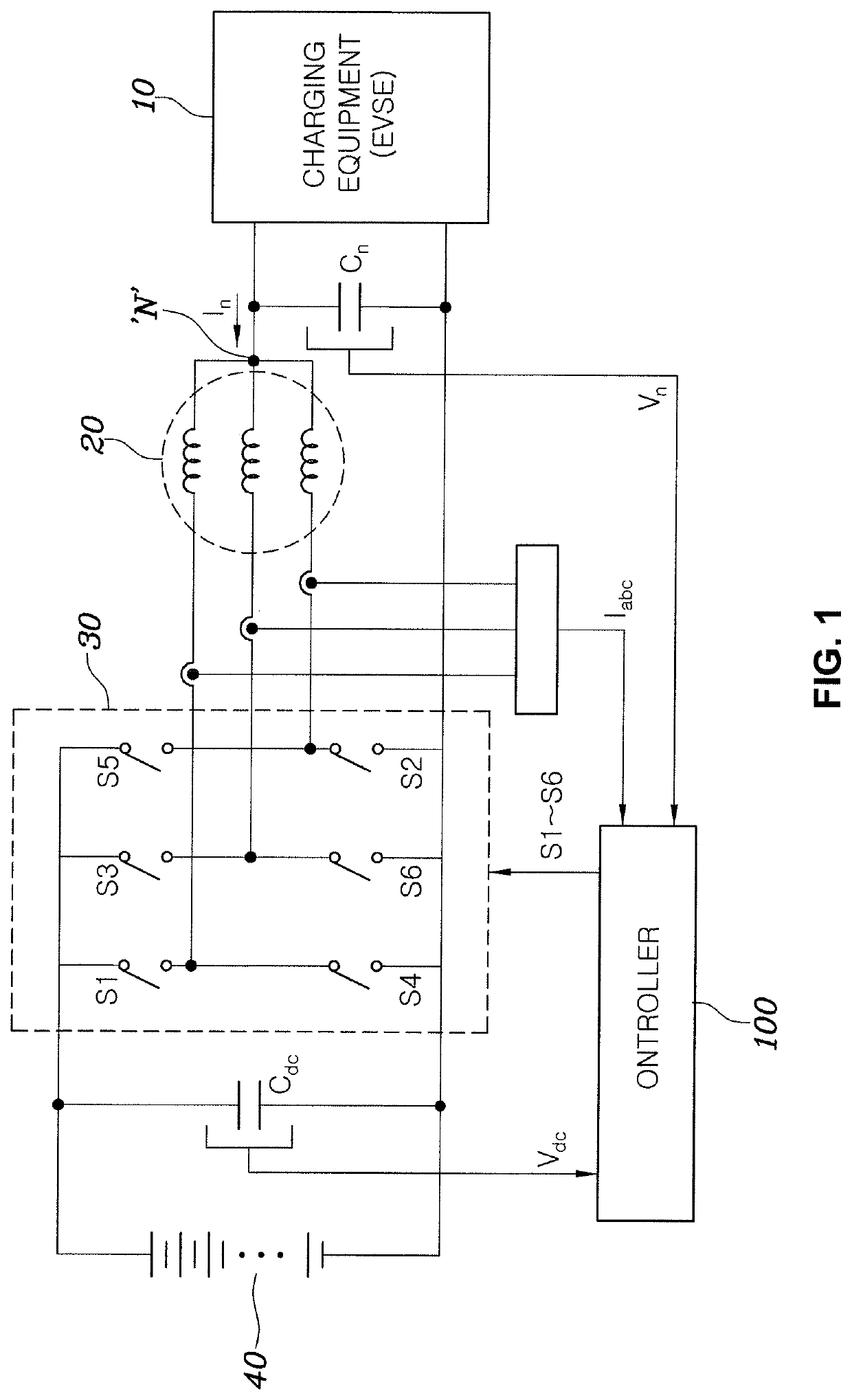
[0009]Various aspects of the present invention are directed to providing a charging system using a motor driving system, which is configured for stably controlling an external charging voltage input to a neutral point of a motor, reducing current imbalance of each phase and improving charging efficiency of a battery.

Problems solved by technology

However, since a high-capacity booster converter for boosting a voltage of 400 V to 800 V or more has a large weight and volume and is expensive, it may be difficult to provide the high-capacity booster converter in a vehicle.
Furthermore, the price of a vehicle may increase.
Generally, there is a demand for new charging technology for receiving the voltage of conventional charging equipment for providing a relatively low charging voltage, boosting the voltage to a high voltage without additionally providing an additional apparatus or further increasing cost and supplying the high voltage to a battery.

Method used


Image

  • Charging system using motor driving system
  • Charging system using motor driving system
  • Charging system using motor driving system

Examples


Embodiment Construction

[0028]Reference will now be made in detail to various embodiments of the present invention(s), examples of which are illustrated in the accompanying drawings and described below. While the present invention(s) will be described in conjunction with exemplary embodiments of the present invention, it will be understood that the present description is not intended to limit the present invention(s) to those exemplary embodiments. On the other hand, the present invention(s) is / are intended to cover not only the exemplary embodiments of the present invention, but also various alternatives, modifications, equivalents and other embodiments, which may be included within the spirit and scope of the present invention as defined by the appended claims.

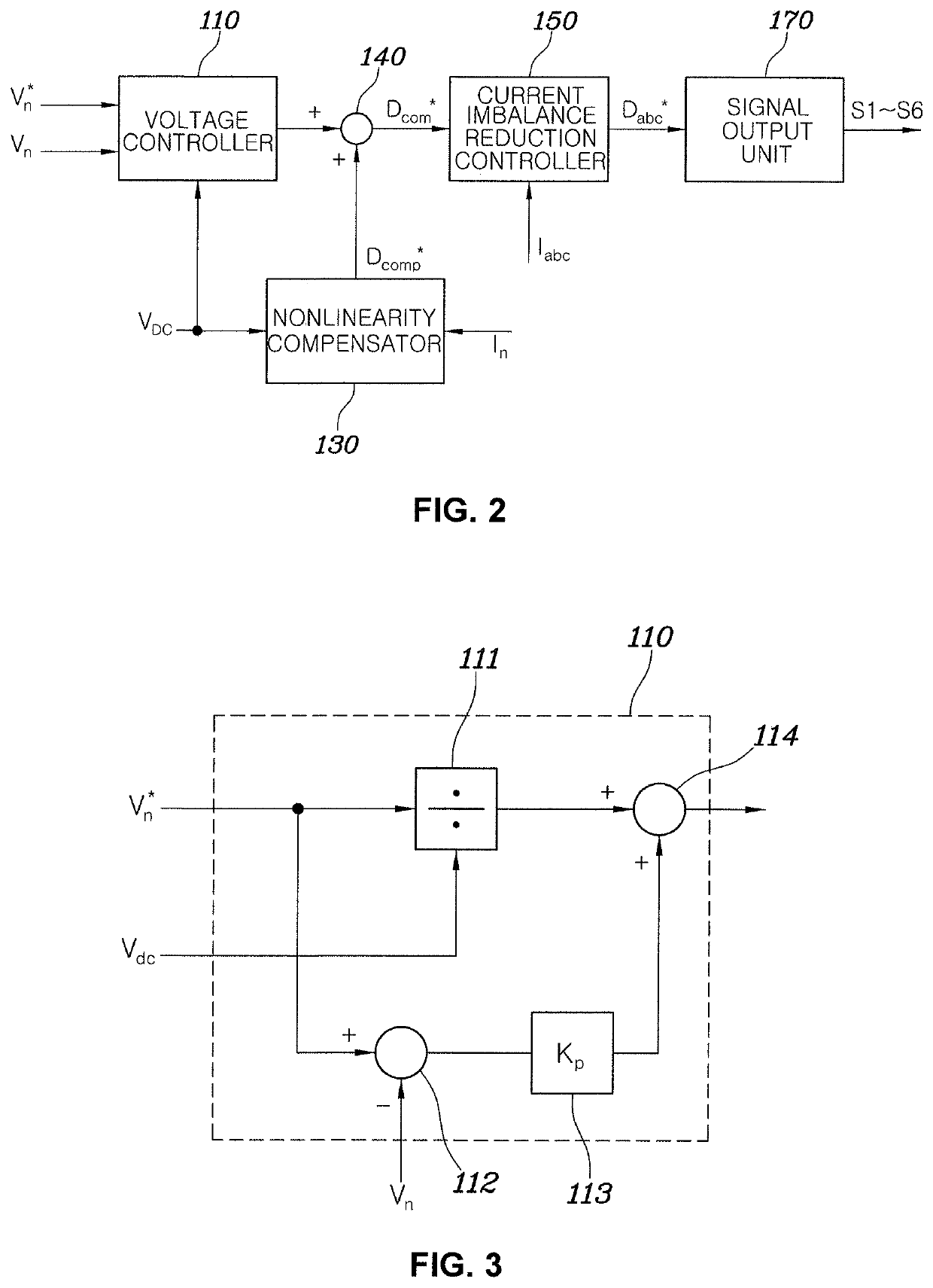
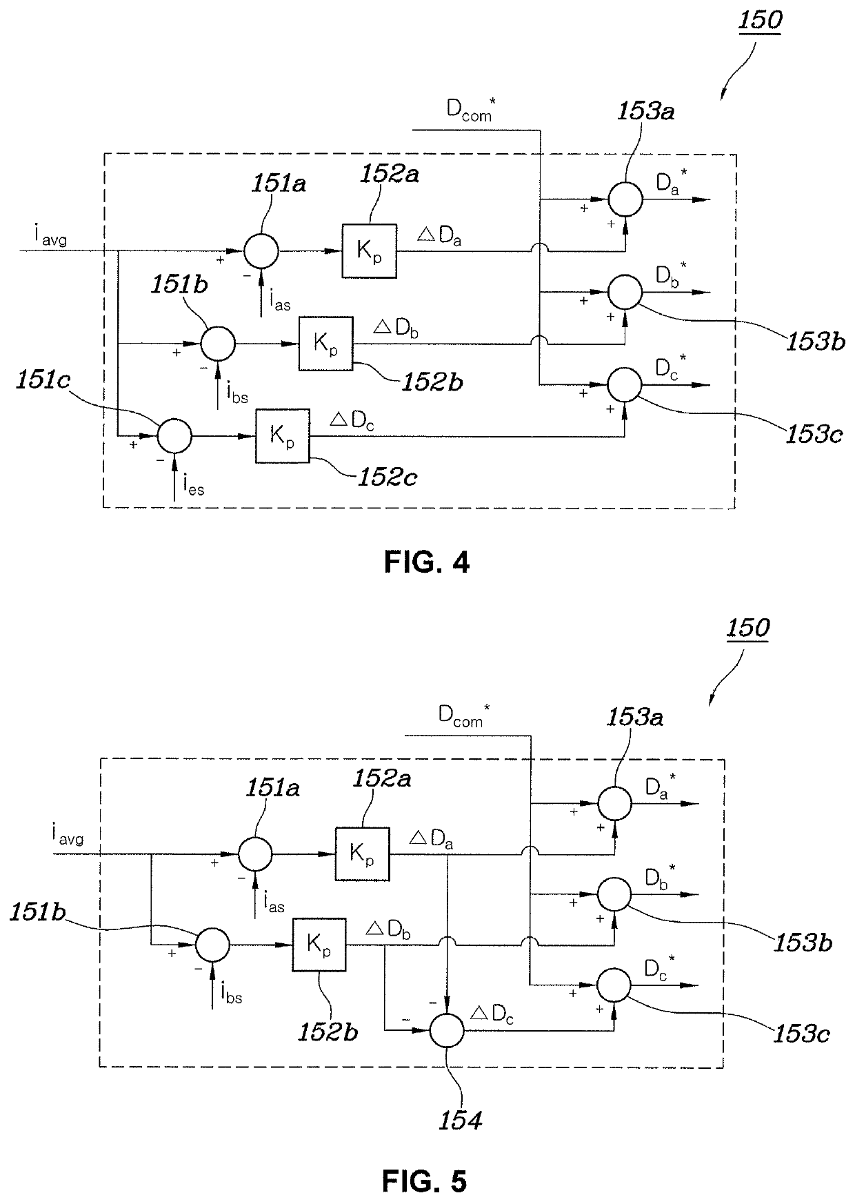
[0029]Hereinafter, a charging system using a motor driving system according to various embodiments will be described with reference to the accompanying drawings.

[0030]FIG. 1 is a circuit diagram of a charging system using a motor driving system acc...


PUM


Abstract

A charging system using a motor driving system, the motor driving system including: a battery and an inverter, the inverter configured to receive and convert a direct current (DC) power stored in the battery into a three-phase alternating current (AC) power and to output the three-phase AC power to a motor when the motor is driven and the motor configured to generate a rotation force using the three-phase AC power output from the inverter, the charging system includes a controller configured to control the inverter to boost a voltage at a neutral point of the motor and to output the boosted voltage to the battery by determining duty values of switching elements in the inverter when an external charging current is provided to the neutral point of the motor.

Description

CROSS REFERENCE TO RELATED APPLICATION[0001]The present application claims priority to Korean Patent Application No. 10-2018-0154797 filed on Dec. 4, 2018, the entire contents of which is incorporated herein for all purposes by this reference.BACKGROUND OF THE INVENTIONField of the Invention[0002]The present invention relates to a charging system using a motor driving system and, more particularly, to a charging system using a motor driving system, which is configured for stably controlling an external charging voltage input to a neutral point of a motor, reducing current imbalance and improving charging efficiency.Description of Related Art[0003]In general, electric vehicles or plug-in hybrid electric vehicles perform battery charging, by converting power received from external charging equipment into a state suitable for battery charging and supplying power to a battery.[0004]For example, conventional charging equipment for rapid charging was manufactured to output a voltage of 40...

Claims


Application Information

Patent Timeline
Patent Type & Authority Patents(United States)
IPC IPC(8): H02J7/16H02J7/04H02P27/06B60L53/22B60L58/13
CPCH02J7/16B60L53/22B60L58/13H02J7/04H02P27/06B60L2210/42B60L53/24B60L3/0061B60L2210/14B60L2210/40H02J7/02H02J2207/20H02J2310/48Y02T10/70Y02T10/7072Y02T10/72Y02T90/14B60Y2200/91B60Y2200/92B60L50/51
Inventor LEE, YONG JAEPARK, JOO YOUNGHWANG, JAE HOKWAK, MU SHINBAE, SU HYUN
Owner HYUNDAI MOTOR CO LTD
Why Eureka
Eureka Blog
Learn More