
A high-efficiency oil-immersed transformer with fast exhaust

An oil-immersed transformer, high-efficiency technology, applied in the direction of transformer/inductor cooling, etc., can solve problems such as low work efficiency, reduced purity, and reduced oil insulation, and achieve the effects of improving work efficiency, shortening power outage time, and improving purity

Active Publication Date: 2021-02-09
江苏凡高电气有限公司
View PDF12 Cites 1 Cited by
  • Summary
  • Abstract
  • Description
  • Claims
  • Application Information

AI Technical Summary

Problems solved by technology

[0002] The transformer is a device that uses the principle of electromagnetic induction to change the AC voltage. With the continuous development of the national grid, the transformer has become an indispensable equipment in circuit transmission. Among them, the oil-immersed transformer has become the choice of the majority of users due to its strong performance and easy maintenance. One, but the current technical considerations are not perfect, and it has the following disadvantages: After the oil-immersed transformer has been used for a long time, impurities will be generated in the oil tank and precipitated at the bottom, and it is necessary to drain the oil and then refuel to ensure the normal operation of the transformer. During the oil change process, the transformer oil is easy to mix with air and flow into the oil tank. The purity of the transformer oil in the transformer will be reduced, and the insulation of the transformer oil containing air will also be reduced, which will easily cause the transformer to be damaged. Therefore, the transformer oil in the transformer oil tank After the oil change, it needs to stand still for a few hours and wait for the air bubbles to be automatically discharged before starting the transformer to start working, which has low working efficiency

Method used


Image

  • A high-efficiency oil-immersed transformer with fast exhaust
  • A high-efficiency oil-immersed transformer with fast exhaust
  • A high-efficiency oil-immersed transformer with fast exhaust

Examples


Embodiment

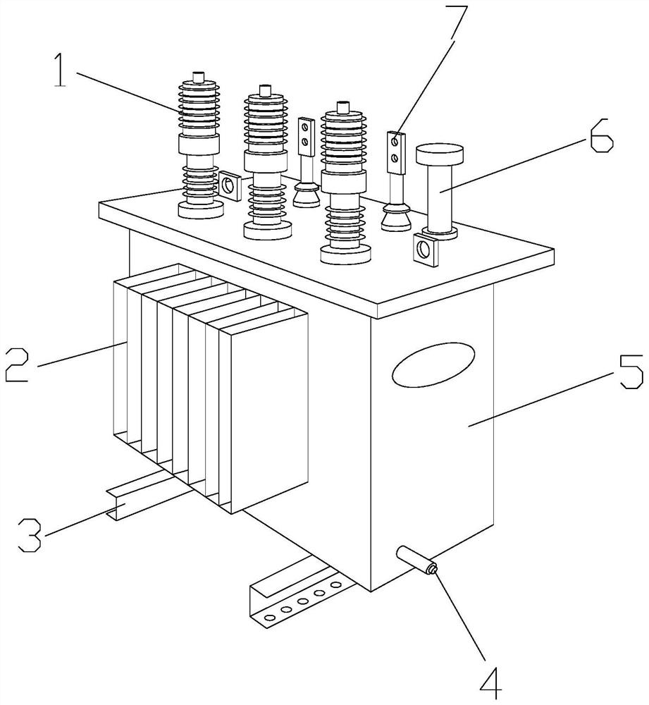
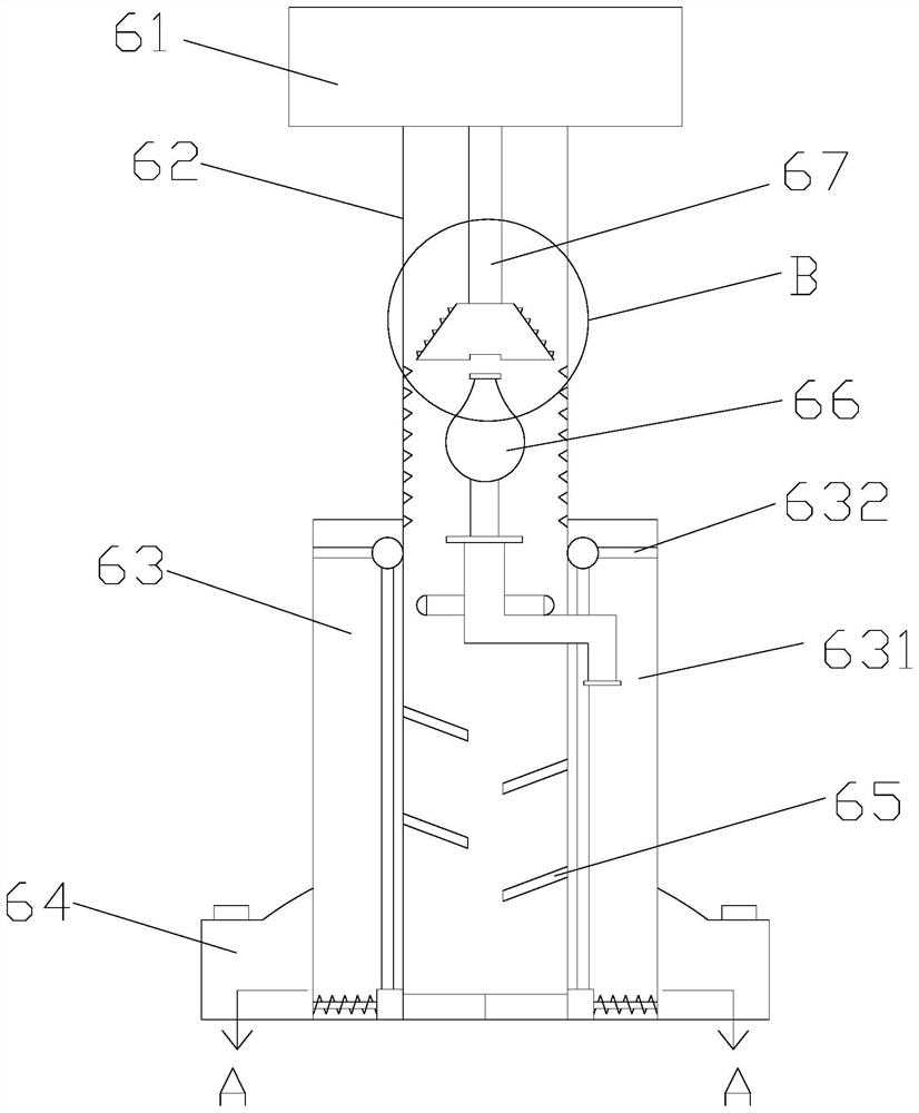
[0026]SeeFigure 1-Figure 2 , The present invention provides a high-efficiency oil-immersed transformer that can quickly exhaust gas. Its structure includes high-voltage terminal 1, heat sink 2, fixed base 3, oil drain pipe 4, fuel tank body 5, oil filling pipe 6, low-voltage connection terminal 7, and The fuel tank body 5 has a rectangular structure, the fixed base 3 is provided with two fixed bases which are welded to the left and right ends of the bottom surface of the fuel tank body 5, the heat dissipation plate 2 is located between the front and rear surfaces of the fuel tank body 5, and the high-voltage terminal 1 is provided with Three are respectively located on the upper surface of the tank body 5. The low-voltage terminal 7 is installed behind the high-voltage terminal 1 and parallel to the high-voltage terminal 1, the drain pipe 4 is welded to the bottom of the right side of the fuel tank body 5. 6 Vertically installed at the upper right corner of the upper surface of the ...


PUM


Abstract

The invention discloses a high-efficiency oil-immersed transformer capable of rapid exhaust. The rectifying fins, exhaust structure, and oil guiding device are coordinated. When the transformer needs to be repaired and refueled, the staff will directly pour new transformer oil into the main body of the oil tank from the oil filling pipe, and the residual air bubbles in the transformer oil can be directly passed through the exhaust structure. Discharge improves the purity of the newly added transformer oil. After refueling, the transformer can be started to work, reducing the time for waiting for the air bubbles to be discharged by themselves, shortening the power outage time caused by transformer maintenance, and improving work efficiency.

Description

Technical field[0001]The invention relates to the field of power equipment, in particular to a high-efficiency oil-immersed transformer capable of rapid exhaust.Background technique[0002]The transformer is a device that uses the principle of electromagnetic induction to change the AC voltage. With the continuous development of the National Grid, the transformer has become an indispensable equipment in circuit transmission. Among them, oil-immersed transformers have become the choice of users due to their strong performance and easy maintenance. One, but the current technical considerations are not perfect, and it has the following shortcomings: oil-immersed transformers will produce impurities in the tank and precipitate at the bottom after a long time of use. The oil needs to be drained to drain the impurities before refueling to ensure the normal operation of the transformer, but During the oil change process, the transformer oil easily mixes with air and flows into the oil tank. ...

Claims


Application Information

Patent Timeline
Patent Type & Authority Patents(China)
IPC IPC(8): H01F27/14
CPCH01F27/14
Inventor 曾剑成
Owner 江苏凡高电气有限公司
Learn More