Rainwater collection and purification device and method
A rainwater collection and purification device technology, applied in water supply devices, drinking water devices, chemical instruments and methods, etc., can solve problems such as low rainwater collection efficiency, achieve high rainwater collection efficiency, save occupied space, and improve rainwater collection efficiency. Effect
- Summary
- Abstract
- Description
- Claims
- Application Information
AI Technical Summary
Problems solved by technology
Method used
Image


Examples
Embodiment 1
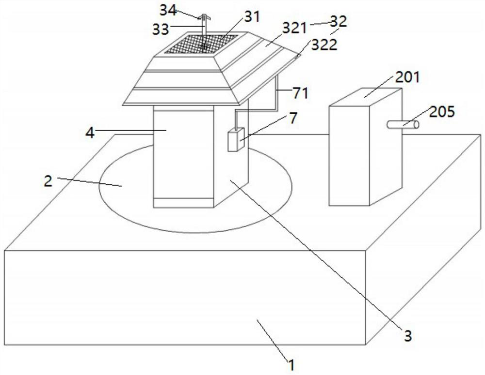
[0046] Such as figure 1 , figure 2 The illustrated embodiment is a rainwater collection and purification device, comprising a reservoir 1, a turntable 2 arranged on the reservoir, a vertical cylinder 3 arranged on the rotary disk, a filter screen 31 arranged on the opening at the upper end of the vertical cylinder, The water collecting cover 32 that is located at the upper end of the vertical tube, the vertical tube 33 with the upper end and the lower end closed above the opening, 6 nozzles 34 that are located on the vertical tube, and the solar panel 4 that is located on the vertical tube; also includes The storage battery, the controller 6, and the turntable are slidingly connected with the guide rails arranged on the reservoir. The cross-section of the vertical cylinder is rectangular. A rectangular ring-shaped support frame 322, the two cylinders 7 located on the opposite sides of the vertical tube are respectively connected to the support frame on the upper edge of the ...
Embodiment 2
[0058] Embodiment 2 includes all structure and method parts of embodiment 1, such as Figure 4 , Figure 5 As shown, a column 101 is provided on the turntable on the outside of the vertical tube in Embodiment 2, a windward plate 102 is provided on the column, a trumpet-shaped air inlet hood 103 is arranged on the top of the windward plate, and a flexible material is used at the rear of the air inlet hood. The formed arc tube 104 has an opening at the rear end of the arc tube, and the size of the air inlet of the air inlet hood is greater than the size of the air outlet of the air inlet hood.
[0059] Such as Figure 7 As shown, the condensing shell is in the shape of a hemisphere arched downwards, and the space enclosed between the condensing shell and the upper end of the box is filled with water. The distilled water collection box is circular with an open upper end. The column is connected to the bottom of the condensing shell, and there is a gap between the upper edge of ...
Embodiment 3
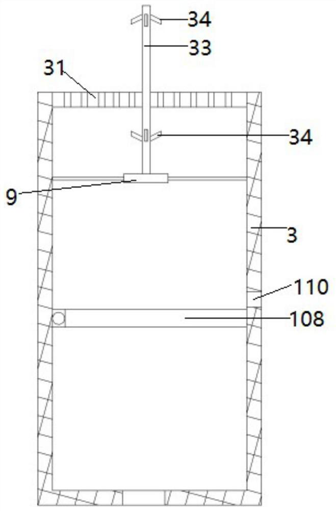
[0064] Embodiment 3 includes all structure and method parts of embodiment 1, as figure 2 , image 3 The turntable of the shown embodiment 3 is provided with an air bag 105, a vertical rod 106 is provided on the rotary table, a cavity 1061 is provided in the vertical rod, a guide rod 1062 and a piston plate 1063 are provided in the cavity, and an alarm is provided at the upper end of the cavity The button 1071 of 107, the air bag communicates with the lower part of the cavity; the bottom of the vertical tube is provided with a flip cover 108, the flip cover is connected with the vertical tube through the rotating shaft, the vertical tube is provided with a second motor, the second motor is connected with the rotating shaft, and the vertical tube One side is provided with a drain port 110, and the buttons, the alarm and the second motor are all electrically connected to the controller. The second motor is connected with the inner wall of the vertical cylinder through a plurali...
PUM
 Abstract
Description
Claims
Application Information
 - R&D
- Intellectual Property
- Life Sciences
- Materials
- Tech Scout
- Unparalleled Data Quality
- Higher Quality Content
- 60% Fewer Hallucinations
Browse by: Latest US Patents, China's latest patents, Technical Efficacy Thesaurus, Application Domain, Technology Topic, Popular Technical Reports.
© 2025 PatSnap. All rights reserved.Legal|Privacy policy|Modern Slavery Act Transparency Statement|Sitemap|About US| Contact US: help@patsnap.com