
Pixel structure, display panel and display device

A technology of pixel structure and display panel, which is applied in the field of display panel and display device, and pixel structure, and can solve the problems such as unevenness of the edge of the display area, and achieve the effect of eliminating the unevenness

Active Publication Date: 2020-09-08
SHENZHEN CHINA STAR OPTOELECTRONICS SEMICON DISPLAY TECH CO LTD
View PDF9 Cites 0 Cited by
  • Summary
  • Abstract
  • Description
  • Claims
  • Application Information

AI Technical Summary

Problems solved by technology

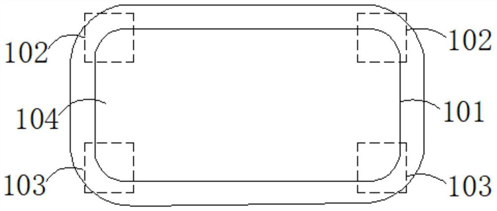
[0005] The present disclosure provides a pixel structure, a display panel and a display device, which are used to solve the problem that the edge of the display area of ​​the display panel in the prior art is not smooth

Method used


Image

  • Pixel structure, display panel and display device
  • Pixel structure, display panel and display device
  • Pixel structure, display panel and display device

Examples


Embodiment Construction

[0027] The following descriptions of the various embodiments refer to the accompanying drawings to illustrate specific embodiments in which the present disclosure may be practiced. The directional terms mentioned in this disclosure, such as [up], [down], [front], [rear], [left], [right], [inner], [outer], [side], etc., are only for reference Additional schema orientation. Accordingly, the directional terms used are used to describe and understand the present disclosure, rather than to limit the present disclosure. In the figures, structurally similar elements are denoted by the same reference numerals.

[0028] The present disclosure will be further described below in conjunction with the accompanying drawings and specific embodiments:

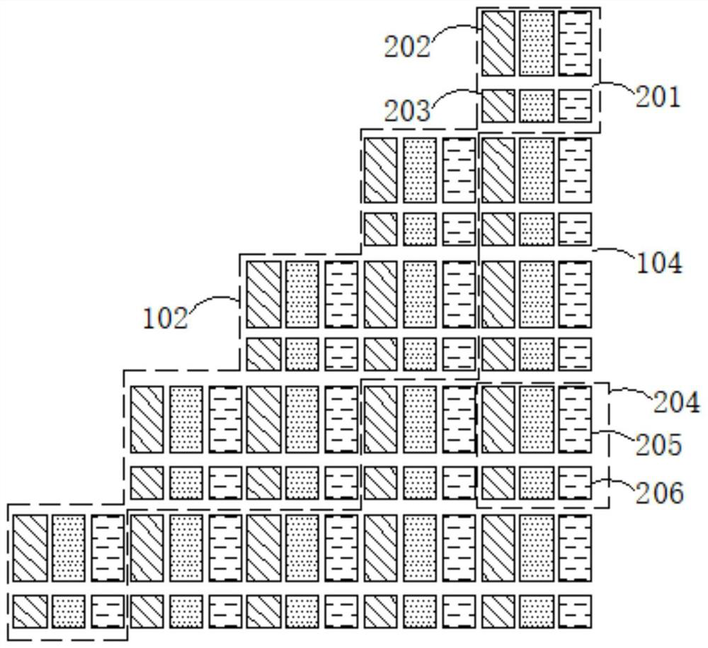
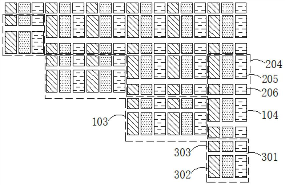
[0029] Embodiments of the present disclosure provide a pixel structure, which is combined below Figure 1 to Figure 3 Explain in detail.

[0030] like figure 1 shown, figure 1 It is a schematic diagram of a pixel structure 101 provided i...


PUM


Abstract

A pixel structure (101), a display panel, and a display device. The pixel structure (101) comprises: a first boundary portion (102) comprising a plurality of first sub-pixels (201), each first sub-pixel (201) comprising a first main pixel portion (202) and a first slave pixel portion (203); and a second boundary portion (103) comprising a plurality of second sub-pixels (301), each second sub-pixel (301) comprising a second main pixel portion (302) and a second slave pixel portion (303).

Description

technical field [0001] The present invention relates to the field of display technology, and in particular, to a pixel structure, a display panel and a display device. Background technique [0002] With the development of smart technology, wearable devices are becoming more and more popular, and with the development of wearable electronic products, the human-computer interaction interface of these wearable devices no longer uses traditional rectangular panels, but more and more use Special-shaped cut panels, including round, octagonal and even special-shaped corners, can meet the wearable performance of smart devices or meet their stylish design. [0003] However, in the prior art, a special-shaped display panel includes a display area, a black matrix area and a transition area. In order to avoid light leakage, the transition area also needs to be filled with a black matrix material. Based on this structure, since the conventional pixel shape is a rectangle, in order to mee...

Claims


Application Information

Patent Timeline
Patent Type & Authority Patents(China)
IPC IPC(8): G09F9/302
CPCG09F9/302
Inventor 刘林峰
Owner SHENZHEN CHINA STAR OPTOELECTRONICS SEMICON DISPLAY TECH CO LTD
Learn More