A dual-purpose open and close low-velocity return wind tunnel

A low-speed, wind tunnel technology, applied in the field of wind tunnel experiments, can solve the problems of a large amount of time and manpower, long experiment preparation time, etc., and achieve the effect of reducing experiment preparation time, time and manpower expenditure

Inactive Publication Date: 2020-09-01
SHENYANG AEROSPACE UNIVERSITY
View PDF8 Cites 0 Cited by
  • Summary
  • Abstract
  • Description
  • Claims
  • Application Information

AI Technical Summary

Problems solved by technology

[0006] However, for the traditional low-velocity recirculation wind tunnel, in order to meet different experimental needs, it is usually necessary to refit the closed low-velocity recirculation wind tunnel and the open low-velocity recirculation wind tunnel, and the refitting process usually requires a lot of time and manpower , and lead to longer experiment preparation time

Method used


Image

  • A dual-purpose open and close low-velocity return wind tunnel
  • A dual-purpose open and close low-velocity return wind tunnel
  • A dual-purpose open and close low-velocity return wind tunnel

Examples


Embodiment Construction

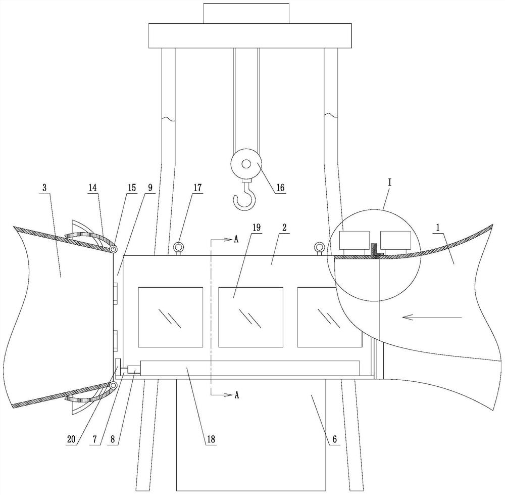
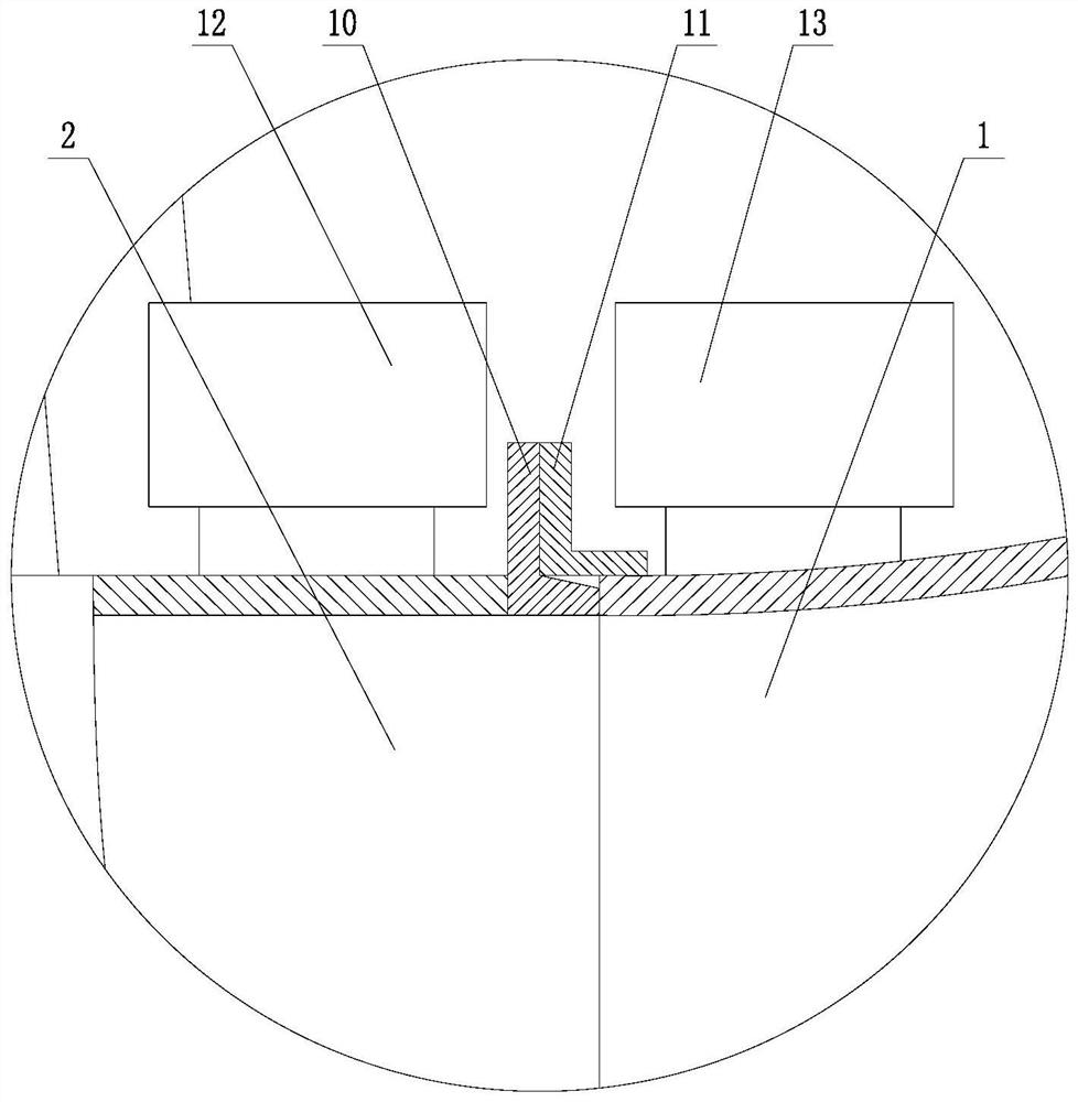
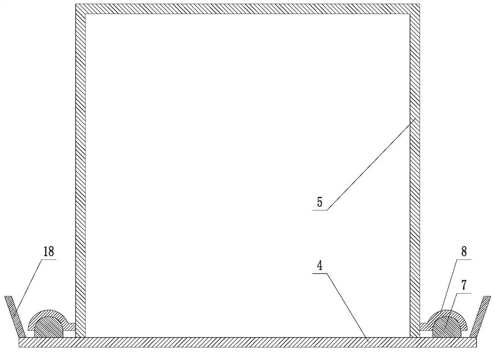
[0023] The present invention will be further described in detail below in conjunction with the accompanying drawings and specific embodiments.

[0024] Such as Figure 1~4 As shown, a dual-purpose low-velocity return wind tunnel for opening and closing includes a contraction section 1, an experiment section 2, and a diffusion section 3. The contraction section 1, experiment section 2, and diffusion section 3 are distributed along a straight line, and the contraction section 1 and Diffusion section 3 is all fixed on the ground; Described experimental section 2 is divided into base plate 4 and upper cover 5, and base plate 4 is fixed on the ground by supporting base 6; Described upper cover 5 is fastened on the base plate 4, and upper cover 5 is connected When the bottom plate 4 is in the buckled state, it constitutes a complete experimental section 2; two parallel slide rails 7 are horizontally installed on the upper surface of the bottom plate 4, and slide plates 8 are respect...


PUM


Abstract

The invention provides an opening and closing dual-purpose low-speed return flow tunnel. An experimental section is divided into a bottom plate and an upper cover; the bottom plate is fixedly arrangedon the ground, and the upper cover and the bottom plate are in buckling fit to form the experimental section; the upper cover can move on the bottom plate through a sliding rail, and the experimentalsection and a contraction section are in inserting fit through an inserting ring and a butting ring; a pressure balance gap is reserved between the experimental section and a diffusion section; the top, adjacent to the inserting ring, of the upper cover and the top, adjacent to the butting joint, of the contraction section are each provided with an electromagnet mechanism, and the two electromagnet mechanisms are arranged in a directly-facing mode, are matched with each other, and can output homopolar repulsion or heteropole attraction electromagnetic force; four gas collecting plates are arranged on the periphery of a hole in the gas inlet end of the diffusion section, the gas collecting plates located at the top, the front end and the rear end of the hole are connected with the hole inthe gas inlet end of the diffusion section through hinges, the gas collecting plate located at the bottom end of the hole is fixedly connected, and the four gas collecting plates form a complete gas collecting hood when being in a spliced mode; and a portal crane is erected above the experimental section, a lifting ring is mounted at the top of the upper cover of the experimental section, and theupper cover is hoisted and transferred through the portal crane.

Description

technical field [0001] The invention belongs to the technical field of wind tunnel experiments, in particular to an open and close dual-purpose low-speed return wind tunnel. Background technique [0002] Wind tunnel is a kind of pipeline test equipment that can artificially generate and control airflow. It can simulate the flow of gas around aircraft or objects, measure the effect of airflow on objects and observe physical phenomena. It is an important test method for the utilization of wind energy, environmental protection, and sports development. [0003] In the wind tunnel experiment, the experimental object is usually fixed in the experimental section of the wind tunnel, and various measuring devices are used to obtain the target parameters. There are many types of wind tunnels, which can be divided into low-speed wind tunnels (Ma≤0.4), high-speed wind tunnels (Ma=0.4~0.5) and hypersonic wind tunnels (Ma≥0.5 ). [0004] Since the world's first wind tunnel was built in...

Claims


Application Information

Patent Timeline
Patent Type & Authority Patents(China)
IPC IPC(8): G01M9/02
CPCG01M9/02
Inventor 李国文朱建勇王成军张庆营
Owner SHENYANG AEROSPACE UNIVERSITY
Why Eureka
Try Eureka