Retracting and releasing method of submersible vehicle

A technology of submersibles and retractable devices, which is applied in the field of deployment and recovery on the water surface, and can solve the problems of unsatisfactory recovery and deployment of multi-joint submersibles, sensor damage on the surface of multi-joint submersibles, and failure of multi-joint submersible retraction and deployment. and other problems, to achieve the effect of high degree of automation, convenient and reliable use, and easy storage and storage

Inactive Publication Date: 2019-07-23
TIANJIN UNIV
View PDF5 Cites 7 Cited by
  • Summary
  • Abstract
  • Description
  • Claims
  • Application Information

AI Technical Summary

Problems solved by technology

Especially when it comes to multi-joint submersibles, such as the patent (Patent No.: CN106744258A) of "A Structure-Adjustable Submersible Suspension-type Recovering Device and Method" (Patent No.: CN106744258A) adopts a cage-type recovery device, which is easy for multi-joint The sensors on the surface of the submersible cause damage, which can easily damage the submersible
For example, the patent "deployment and recovery device for autonomous underwater vehicles" (patent number: 202379064U) has only two sets of grasping arms, which cannot satisfy the recovery and deployment of multi-joint submersibles
[0004] The existing working device can no longer satisfy the retraction and deployment of the multi-joint submersible. At the same time, in order to improve the working efficiency and safety of the deep-sea retraction of the submersible, prevent the submersible from violent swings during the retraction process, and avoid the submersible from being hit, Need more advanced submersible retractable device and control method

Method used


Image

  • Retracting and releasing method of submersible vehicle
  • Retracting and releasing method of submersible vehicle
  • Retracting and releasing method of submersible vehicle

Examples


Embodiment Construction

[0035] The present invention will be described in further detail below in conjunction with the accompanying drawings and the specific implementation process.

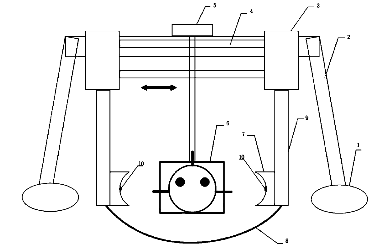
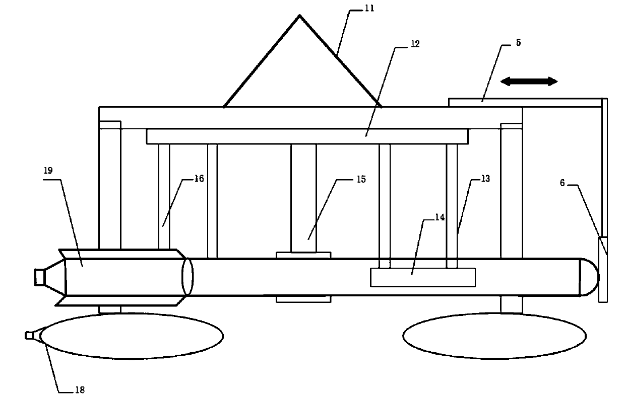
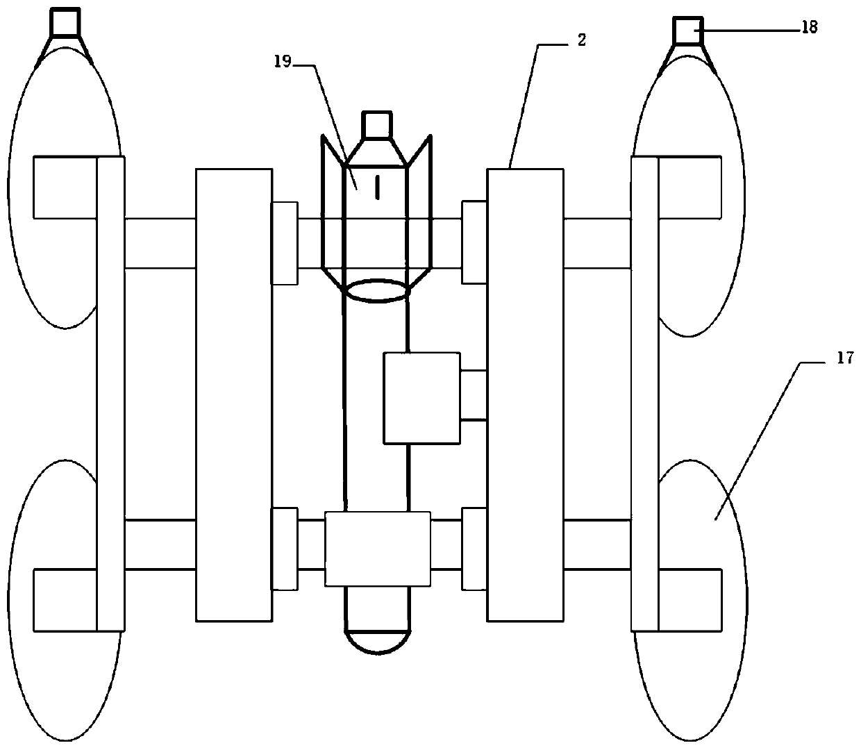
[0036] Such as figure 1 Shown is a submersible retracting device for recovering and deploying a torpedo-shaped submersible 20 . It is composed of a control unit, a pressure sensor 10, a power supply unit, an electric drive unit, a remote controller, and a retractable mechanism. in,

[0037] The retractable mechanism includes a buoyancy base 1, a door bracket 2, a telescopic platform 3, an extension arm 5, a limit facility 6, a gripping arm 9, etc. The bottom of the door bracket 2 is fixedly connected to the buoyancy base 1, and two horizontal Guide rail 4, the telescopic platform is installed on two horizontal guide rails 4, three pairs of grasping arms 9 are arranged under the telescopic platform, and a horizontal guide rail is arranged above the telescopic platform 3, which is connected to the extension arm 5, which...


PUM


Abstract

The invention relates to a retracting and releasing method of a submersible vehicle. A submersible vehicle retracting and releasing device adopted by the method comprises a control unit, a pressure sensor, a power supply unit, an electric drive unit and a retracting and releasing mechanism, wherein the retracting and releasing mechanism comprises a buoyancy base, a support, a telescopic platform,an extension arm and a grabbing arm. The deployment process of the submersible vehicle comprises the steps that the submersible vehicle is fixed on the submersible vehicle retracting and releasing device, the pressure between a contact plate and the submersible vehicle is adjusted to be within a safe range, the front end of the submersible vehicle is fixed by a limiting facility, and the submersible vehicle retracting and releasing device is hoisted with the submersible vehicle together on the water surface; the submersible vehicle retracting and releasing device is driven to a preset water surface; under the action of the control unit, an extension arm servo motor acts and moves forwards along a guide rail, the limiting facility leaves the front part of the submersible vehicle, a cable servo motor acts to loosen a bottom cable, the telescopic platform moves towards the two ends along a horizontal guide rail, the grabbing arm acts along with the telescopic platform, the contact plate leaves the submersible vehicle, and the submersible vehicle floats on the deployment water surface.

Description

technical field [0001] The invention belongs to the technical field of water surface deployment and recovery of underwater vehicles. Background technique [0002] The submersible is an active deep diving device with underwater observation and operation capabilities. It is mainly used to perform tasks such as underwater investigation, seabed exploration, and seabed development. In the business process of submersibles, deployment and recovery operations are extremely important links, especially the recovery link, which is directly related to the availability of underwater unmanned vehicles. [0003] Most of the deployment and recovery of submersibles are directly hoisted based on the mother ship crane or A-frame. Due to the strong wind and waves in offshore operations, the submersible swings with the waves on the water surface, which is very dangerous for the staff who launch the operation, and it is not convenient and efficient. At the same time, the structure of submersib...

Claims


Application Information

Patent Timeline
IPC IPC(8): B66C1/42B66C9/14B66C13/06B66C13/44B66C13/48B66C13/50B66C19/00B63C7/16
CPCB63C7/16B66C1/425B66C9/14B66C13/06B66C13/44B66C13/48B66C13/50B66C19/00
Inventor 刘迎澍赵士环孟庆浩任超
Owner TIANJIN UNIV
Why Eureka
Try Eureka