
Stock bin arch breaking device

A silo and arch breaking technology, applied in the field of silo arch breaking equipment, can solve the problems of limited effect, limited effective area, poor effect, etc., and achieve the effects of simple structure, wide application range and convenient production.

Active Publication Date: 2019-07-23
刘怀收
View PDF14 Cites 7 Cited by
  • Summary
  • Abstract
  • Description
  • Claims
  • Application Information

AI Technical Summary

Problems solved by technology

There are limitations in the application of the above three arch breaking methods: Air cannon arch breaking is suitable for silos with relatively large cross-sections. There is a prerequisite for using air cannons to break arches—the material under the arching part must flow normally or be completely emptied. The effect of bombarding with air will be better. If the air cannon is used when the bin mouth is blocked, the arch in the bin will become stronger and stronger, and finally it can only be cleared manually; the loosening machine is driven by a hydraulic cylinder to weld a The push-pull rod of the group scraper moves back and forth to break the arch. Because the stroke of the hydraulic cylinder is limited, it will not exceed half a meter at most, and the width of the scraper is also limited, so the effective area of ​​the loosening machine is very limited, which will affect the slightly arched surface. It has a certain effect, but if the material has a large water content and the arch is strong, the effect of the loosening machine is very limited; the pneumatic hammer is a kind of hammer that uses compressed air as power and is fixed on the side wall of the silo. Its essence is to use pneumatic percussion instead of manual sledgehammer to hit the warehouse wall. The effect is more obvious when the warehouse is slightly blocked, and the effect is very poor when the warehouse is seriously blocked.

Method used


Image

  • Stock bin arch breaking device
  • Stock bin arch breaking device
  • Stock bin arch breaking device

Examples


Embodiment

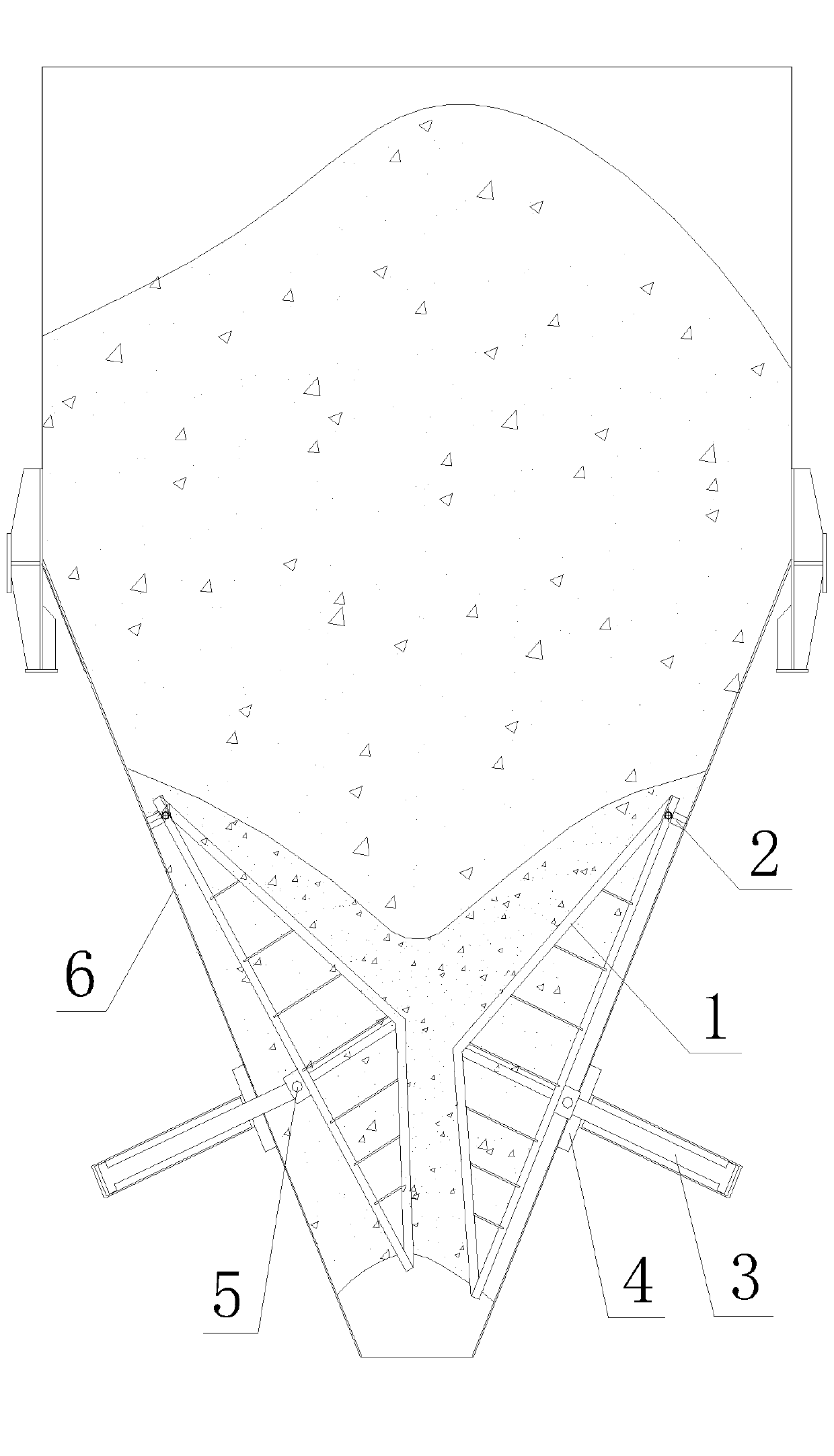
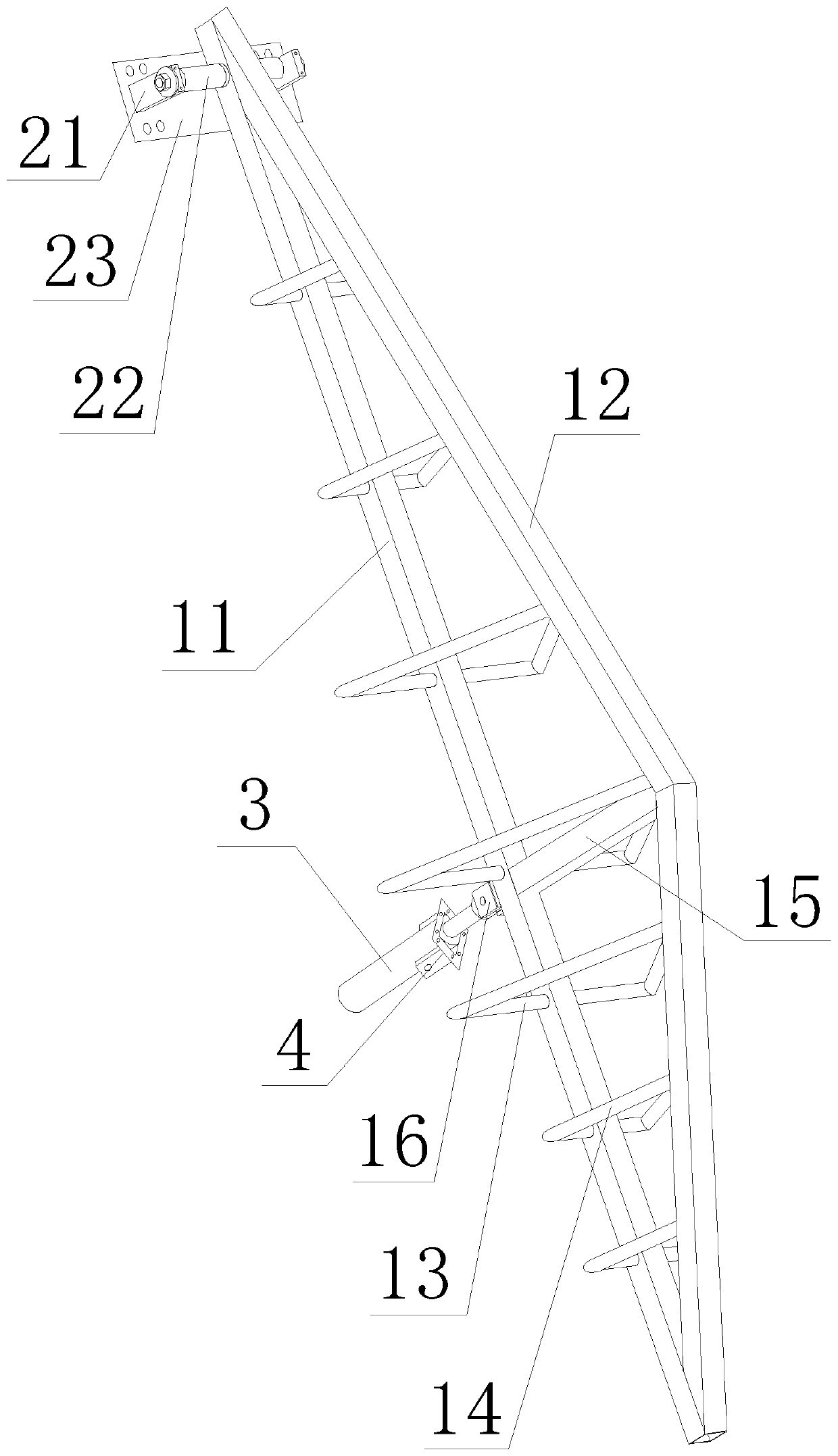
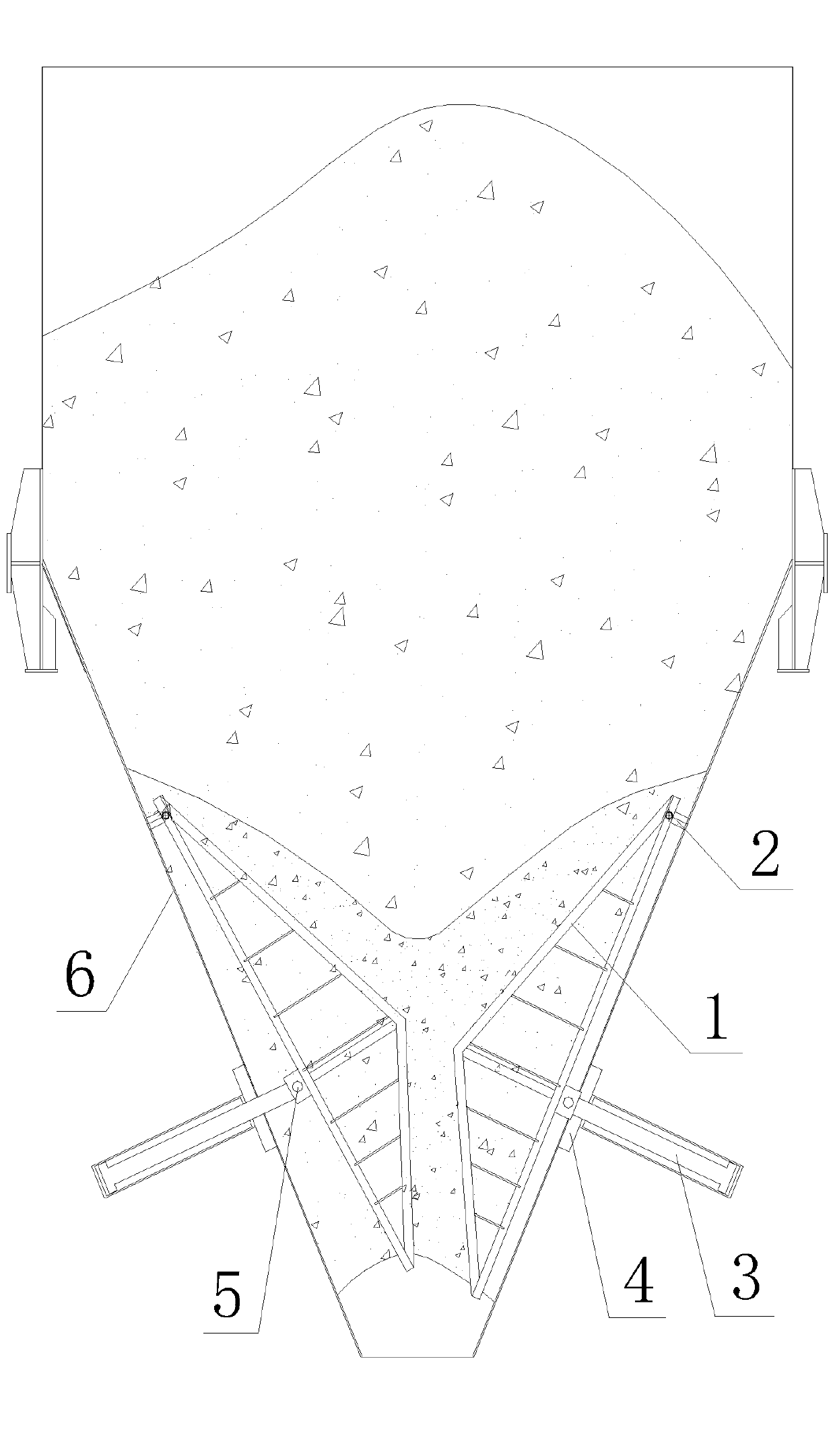
[0022] refer to Figure 1-Figure 2 , the bunker arch breaking device described in this embodiment includes an impact bracket 1 that matches the shape of the bin 6, and the upper part of the impact bracket 1 is connected to the connecting support 2 fixedly assembled on the inner wall of the bin 6. The silo is connected by 6 hinges. The middle and lower part of the impact bracket 1 is equipped with a power drive device that drives the impact bracket 1 to swing and break the arch with the connecting support 2 as the base point, and the power drive device is assembled on the side wall of the silo 6 .

[0023] The impact support 1 includes a main frame, a supporting vertical beam 15 and several supports for increasing the section of the broken arch. in:

[0024] The main frame is in a triangular shape and includes a main frame beam 11 and two main frame side beams 12 , the main frame beam 11 and the two main frame side beams 12 are connected end to end.

[0025] The supporting v...


PUM


Abstract

The invention relates to the technical field of stock bin arch breaking equipment, in particular to a stock bin arch breaking device. The device comprises an impact support matched with the shape of astock bin, the upper part of the impact support is hinged to the stock bin through a connecting support which is fixedly assembled on the inner side wall of the stock bin, the middle lower part of the impact support is provided with a power driving device for driving the impact support to swing by taking the connecting support as a base point for arch breaking, and the power driving device is assembled on the side wall of the stock bin. The impact support is driven to swing back and forth by the power driving device to extrude and impact arch materials, so that the arch materials are effectively broken; and moreover, the device is simple in structure, convenient to manufacture, wide in application range and particularly applicable to breaking the blockage at the opening part of stock bin.

Description

technical field [0001] The invention relates to the technical field of arch breaking equipment for a silo, in particular to an arch breaking device for a silo. Background technique [0002] The silo plays the role of temporarily storing materials in the transportation of materials. When the water content of the material in the silo is high and the time of resting in the silo is long, the material will harden and arch and lose fluidity, especially the silo mouth is most likely to be blocked. [0003] After the silo is arched, the traditional method of breaking the arch of the silo is to manually clear the silo. Manual cleaning of hundreds of thousands of tons of silos is time-consuming, laborious, and costly; moreover, manual clearance is also very dangerous— —It is easy to collapse and bury workers, causing casualties. [0004] At present, there are three methods to solve the arching of silo materials: air cannon, loosening machine and pneumatic percussion hammer. There a...

Claims


Application Information

Patent Timeline
Patent Type & Authority Applications(China)
IPC IPC(8): B65D88/66
CPCB65D88/66
Inventor 刘怀收
Owner 刘怀收
Learn More