Steel pipe cutting device

A cutting device, a technology for steel pipes, applied in the field of steel pipe processing, can solve problems such as trouble, sparks and debris splashing, lack of protective equipment, etc., and achieve the effect of reducing noise

Pending Publication Date: 2019-07-23
HAIYAN HUITONG INTELLIGENT FURNITURE CO LTD
View PDF0 Cites 1 Cited by
  • Summary
  • Abstract
  • Description
  • Claims
  • Application Information

AI Technical Summary

Problems solved by technology

[0002] Existing steel pipe cutting machines are divided into planetary cutting machines, hydraulic cutting machines, external card cutting machines, CNC hydraulic cutting machines, electric cutting machines, pneumatic cutting machines and other models, but the existing cutting machines generally need to be refurbished It is not convenient enough to use clamps alone to tighten steel pipes, and when cutting steel pipes, different clamps need to be used to tighten steel pipes of different thicknesses, which is troublesome; and in the cutting process, due to the lack of necessary protective equipment, cutting The spark debris generated during the process splashes everywhere, causing pollution to the surrounding environment

Method used


Image

  • Steel pipe cutting device
  • Steel pipe cutting device
  • Steel pipe cutting device

Examples


Embodiment

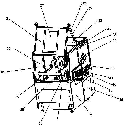
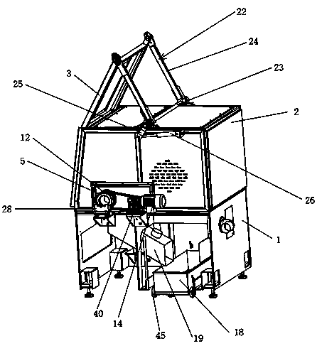
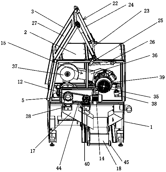
[0029] Embodiment: a kind of steel pipe cutting device, as attached Figure 1-8 Shown, comprise frame 1, the top of frame 1 is provided with protective cover 2, and the sidewall of protective cover 2 is provided with flip 3; There is a steel pipe positioning mechanism 4, such as Figure 6As shown, the steel pipe positioning mechanism 4 includes a positioning tube 5 that is fixed on the side wall of the protective cover 2 through a bearing seat, and the inner end of the positioning tube 5 is provided with a disc-shaped central block 6 with a through hole in the middle. The inside of the block 6 is provided with a bevel gear 7, and the side wall of the bevel gear 7 is provided with a spiral groove 8; the outer wall of the central block 6 is provided with a plurality of limiting chute 9 connected with the through hole, the limiting chute 9 is embedded with a block 10, and the bottom of the block 10 is provided with a convex line 11 that matches the spiral groove 8; the outer end...


PUM


Abstract

The invention discloses a steel pipe cutting device comprising a rack. The top of the rack is provided with a protective cover, and the side wall of the protective cover is provided with an overturning cover; a steel pipe positioning mechanism is arranged at the top of the rack and located in an inner cavity of the protective cover, the steel pipe positioning mechanism comprises a positioning pipefixed to the side wall of the protective cover through a bearing seat, the inner end portion of the positioning pipe is provided with a disc-shaped central block provided with a through hole in the middle, the inner part of the central block is provided with a bevel gear, and the side wall of the bevel gear is provided with a spiral groove; the outer side wall of the central block is provided with a plurality of limiting sliding slots connected with the through hole, clamping blocks are embedded in the limiting sliding slots, and the bottoms of the clamping blocks are provided with protrudingstrips matched with the spiral groove; and the top of the rack is provided with a steel pipe cutting mechanism matched with the steel pipe positioning mechanism. According to the steel pipe cutting device, when steel pipes are cut, the steel pipes with different thicknesses can be fixed, and the cutting quality is ensured; and cutting is performed in a closed space, and generated spark debris does not splash everywhere.

Description

technical field [0001] The invention relates to the technical field of steel pipe processing, in particular to a steel pipe cutting device. Background technique [0002] Existing steel pipe cutting machines are divided into planetary cutting machines, hydraulic cutting machines, external card cutting machines, CNC hydraulic cutting machines, electric cutting machines, pneumatic cutting machines and other models, but the existing cutting machines generally need to be refurbished It is not convenient enough to use clamps alone to tighten steel pipes, and when cutting steel pipes, different clamps need to be used to tighten steel pipes of different thicknesses, which is troublesome; and in the cutting process, due to the lack of necessary protective equipment, cutting The spark debris generated in the process splashes everywhere and pollutes the surrounding environment. Contents of the invention [0003] The object of the present invention is to provide a steel pipe cutting ...

Claims


Application Information

Patent Timeline
Patent Type & Authority Applications(China)
IPC IPC(8): B23D21/00B23D33/00B23D33/02
CPCB23D21/00B23D33/00B23D33/02
Inventor 陈志峰
Owner HAIYAN HUITONG INTELLIGENT FURNITURE CO LTD
Why Eureka
Try Eureka