
A safety type power valve for thermal power generation and using method

A safe and electric technology, applied to valve details, valve devices, sliding valves, etc., can solve problems such as gas leakage, incomplete valve closure, slow valve closure, etc., to reduce the impact of thermal expansion and contraction, and reduce manual force , to avoid the effect of lax closure

Active Publication Date: 2020-07-28
NANTONG LIPEI FLUID VALVE IND CO LTD
View PDF5 Cites 0 Cited by
  • Summary
  • Abstract
  • Description
  • Claims
  • Application Information

AI Technical Summary

Problems solved by technology

[0002] Valves used in fluid control systems range from the simplest shut-off valves to various valves used in extremely complex automatic control systems. There are various types and specifications. Valves can be used to control air, water, steam, various corrosive media, For the flow of various types of fluids such as mud, oil, liquid metal, and radioactive media, the existing gas flow valves for thermal power generation are traditional closed valves, which are easily affected by the environment, resulting in incomplete valve closure and gas leakage. , the existing power valves for thermal power generation will generate great resistance when used, resulting in slow valve closure and difficult operation; the existing valves do not have alarm warning devices, and cannot send an alarm in time when the pressure is too high. The staff warned that it would cause immeasurable losses

Method used


Image

  • A safety type power valve for thermal power generation and using method
  • A safety type power valve for thermal power generation and using method
  • A safety type power valve for thermal power generation and using method

Examples


Embodiment Construction

[0023] The following will clearly and completely describe the technical solutions in the embodiments of the present invention with reference to the accompanying drawings in the embodiments of the present invention. Obviously, the described embodiments are only some, not all, embodiments of the present invention. Based on the embodiments of the present invention, all other embodiments obtained by persons of ordinary skill in the art without making creative efforts belong to the protection scope of the present invention.

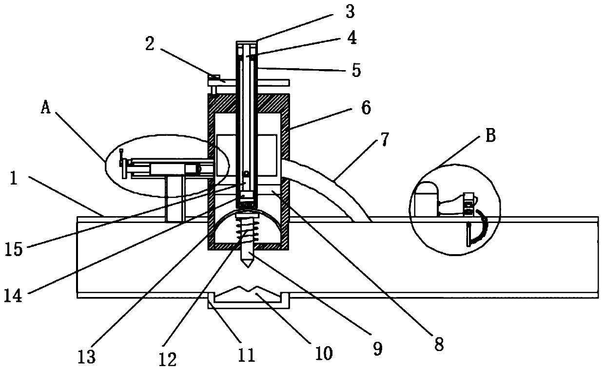
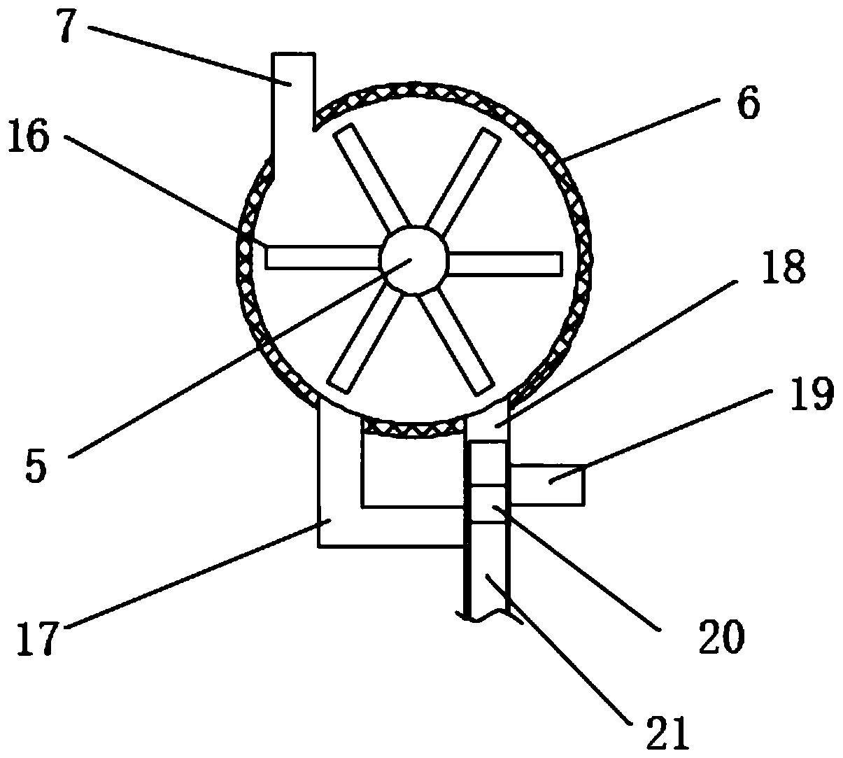
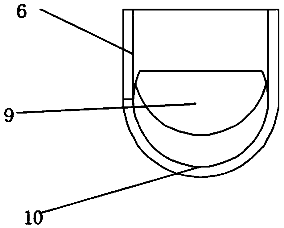
[0024] see Figure 1-6, the present invention provides a technical solution: a safety electric valve for thermal power generation and its use method, including a valve body 1, a positioning plate 2, a rotating cap 3, a rotating rod 4, a pushing screw rod 5, a valve sleeve 6, a row Air pipe 7, first fixed plate 8, gate plate 9, rubber extrusion ring 10, extrusion groove plate 11, extrusion spring 12, rubber pad 13, slider 14, support rod 15, blade 16, first air...


PUM


Abstract

The invention discloses a safety type electric power valve for thermal power generation and a using method thereof. The safety type electric power valve comprises a valve body, a positioning plate, arotary cap, a rotating rod, a pushing and pressing screw rod, a valve sleeve, an exhaust pipe, a first fixing plate, a gate plate, a rubber extrusion ring, an inserting groove, a fixed magnet and an inserting magnet, wherein the valve sleeve is vertically fixed at the top end of the valve body. Due to the fact that a gate valve and a rubber extrusion ring which move up and down are used inside thevalve body, the influence of thermal expansion and cold contraction on the valve is reduced, infirm closing of the valve is avoided, and the safety is improved; during use, the position of a first inserting rod in a second air guide pipe is changed, the inlet direction of the air flow is changed, so that the rotating direction of the pushing and pressing screw rod is changed, the assisting forcefor moving the valve is provided, then closing of the valve is facilitated, the manual force is reduced, and the use is more labor-saving and convenient; and an alarm is arranged, so that when the airpressure is too high, the alarm is triggered, a warning can be sent to a worker, then the worker can maintain and repair, and the safety of thermal power generation can be guaranteed.

Description

technical field [0001] The invention relates to the technical field of electric valve equipment, in particular to a safety type electric valve for thermal power generation and its use method. Background technique [0002] Valves used in fluid control systems range from the simplest shut-off valves to various valves used in extremely complex automatic control systems. There are various types and specifications. Valves can be used to control air, water, steam, various corrosive media, For the flow of various types of fluids such as mud, oil, liquid metal, and radioactive media, the existing gas flow valves for thermal power generation are traditional closed valves, which are easily affected by the environment, resulting in incomplete valve closure and gas leakage. , the existing power valves for thermal power generation will generate great resistance when used, resulting in slow valve closure and difficult operation; the existing valves do not have alarm warning devices, and c...

Claims


Application Information

Patent Timeline
Patent Type & Authority Patents(China)
IPC IPC(8): F16K3/02F16K31/12F16K31/50F16K37/00
CPCF16K3/0254F16K31/12F16K31/50F16K37/0091
Inventor 于亚平王芳刘洪星
Owner NANTONG LIPEI FLUID VALVE IND CO LTD
Learn More