Feeding machine for cabinet production line

A production line and feeding machine technology, applied in the direction of conveyors, conveyor objects, conveyor control devices, etc., can solve the problems of large feeding resistance, sheet damage, and inconvenient sheets, etc., to achieve stable sheet output, safe and convenient use, Avoid the effect of material jam

Pending Publication Date: 2019-07-19
广州市晋丰建材有限公司
View PDF0 Cites 0 Cited by
  • Summary
  • Abstract
  • Description
  • Claims
  • Application Information

AI Technical Summary

Problems solved by technology

[0003] The present invention provides a feeding machine for cabinet production line, which can effectively solve the problem that the existing cabinet production line feeding machine proposed in the above background technology has a simple structure, and it is difficult for the staff to perform accurate positioning when feeding materials, and it is inconvenient to accurately push out. In addition, the existing feeding machine usually pushes the bottom plate in a pile of plates, so that the resistance to feeding is relatively large, which is not conducive to the stable delivery of the plates to the working area. At the same time, there is a certain range of error in the thickness of the plates. The plate thickness difference generated during the feeding process of the existing loading machine cannot be automatically compensated, and material jams are prone to occur, resulting in plate damage and machine shutdown problems

Method used


Image

  • Feeding machine for cabinet production line
  • Feeding machine for cabinet production line
  • Feeding machine for cabinet production line

Examples


Embodiment

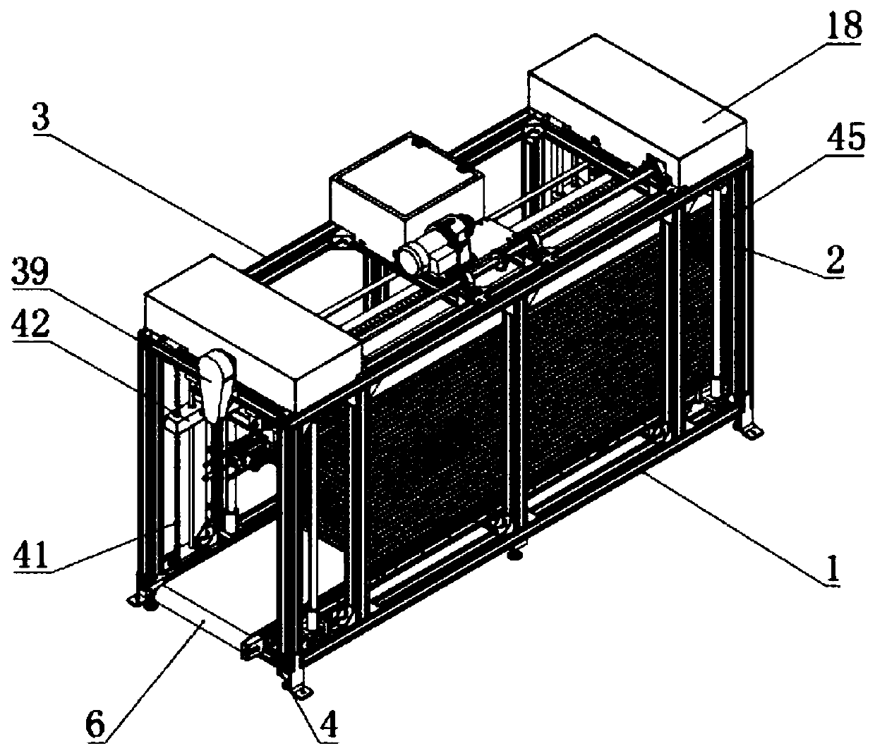
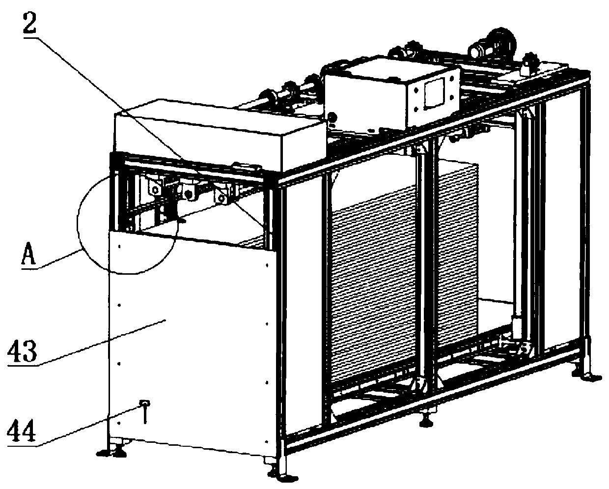
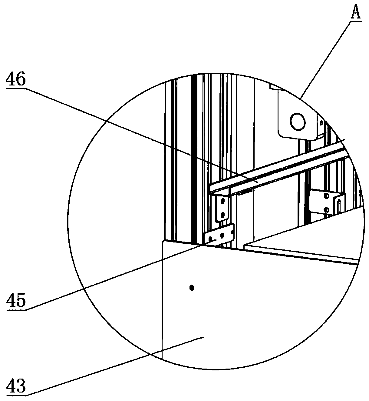
[0040] Example: such as Figure 1-12 As shown, the present invention provides a technical solution, a feeding machine for a cabinet production line, including a bottom frame 1, the top of the bottom frame 1 is installed with a top frame 3 through a support column 2, and the middle part of the top of the bottom frame 1 is symmetrical Mounting frame 4 is installed, and transmission drum 5 is installed equidistantly between two mounting frames 4, and one end of transmission drum 5 of mounting frame 4 ends is equipped with feed motor 47, and transmission drum 5 is wrapped with transmission belt 6 outside measurement, installs The first linear bearing 8 is installed on the surface of one side of the frame 4 through the T-shaped fixing seat 7, and the limit column 9 is installed on the side of the bottom frame 1 corresponding to the position of the first linear bearing 8, and the first linear bearing 8 and the limit Column 9 sliding socket connection.

[0041] The bottom of the mou...


PUM


Abstract

The invention discloses a feeding machine for a cabinet production line. The feeding machine comprises a bottom machine frame, wherein mounting frames are symmetrically arranged in the middle of the top end of the bottom machine frame, transmission rollers are arranged between the two mounting frames at equal intervals, feeding motors are arranged at one ends of the transmission rollers at the endparts of the mounting frames, a conveying belt is wrapped over the outer sides of the transmission rollers, a baffle is arranged between two supporting columns at one end part of the bottom machine frame, and an inductor mounting groove is formed in the bottom of each baffle. The feeding machine is scientific and reasonable, and is safe and convenient to use, inductors are arranged in the inductor mounting grooves, so that a running process of a board on the conveying belt can be stably transmitted into the PLC in a control box; and when the inductors sense that the board is close to the baffles, the PLC controls the feeding motors to stop rotating, so that moving of the conveying belt is stopped, the board is guaranteed to be stably close to the baffles, the board can be conveniently output later, and the material clamping situation caused by the board placing problem is avoided.

Description

technical field [0001] The invention relates to the field of mechanical technology, in particular to a feeding machine for a cabinet production line. Background technique [0002] The cabinet refers to the platform for storing kitchen utensils and cooking operations in the kitchen. It is assembled by many plates. During the production process of the cabinet, the plates need to be transported and moved to the working area for processing. The plates are transported to the processing machine through the feeding machine. To achieve the processing and loading of cabinet panels, but the existing cabinet production line has a simple structure of the feeding machine, and it is difficult for the staff to perform accurate positioning when feeding materials, and it is not convenient to accurately push out the panels, and the existing feeding machine usually pushes a The board at the bottom of the pile of boards, so the resistance to feeding is relatively large, which is not conducive t...

Claims


Application Information

Patent Timeline
Patent Type & Authority Applications(China)
IPC IPC(8): B65G43/08B65G47/82B65G59/02
CPCB65G43/08B65G47/82B65G59/026B65G2203/044B65G2201/022B65G2203/042
Inventor 李伟洪
Owner 广州市晋丰建材有限公司
Why Eureka
Try Eureka