
Voltage measurement device correction method, device and system

A technology of voltage measurement and correction method, which is applied in the direction of measuring devices, measuring electrical variables, instruments, etc., can solve the problem that the single-chip microcomputer can accurately sample the instantaneous value of AC voltage, and the effective value cannot be measured, so as to improve the accuracy and achieve the effect of correction

Active Publication Date: 2019-07-16
SHANDONG JIANZHU UNIV
View PDF9 Cites 7 Cited by
  • Summary
  • Abstract
  • Description
  • Claims
  • Application Information

AI Technical Summary

Problems solved by technology

[0005] In view of the deficiencies in the prior art, to solve the problem that the effective value input by the AC voltage transformer cannot be accurately sampled by the single-chip microcomputer to the instantaneous value of the AC voltage, one or more embodiments of the present disclosure provide a voltage measurement device calibration method, The device and system take into account the nonlinear characteristics of the voltage measurement device and the differences in hardware circuit board welding, and use the signal generator to generate milliampere-level current signals to effectively correct the results of the voltage measurement device and improve its voltage measurement accuracy.

Method used


Image

  • Voltage measurement device correction method, device and system
  • Voltage measurement device correction method, device and system
  • Voltage measurement device correction method, device and system

Examples


Embodiment 1

[0053] According to an aspect of one or more embodiments of the present disclosure, a method for calibrating a voltage measuring device is provided.

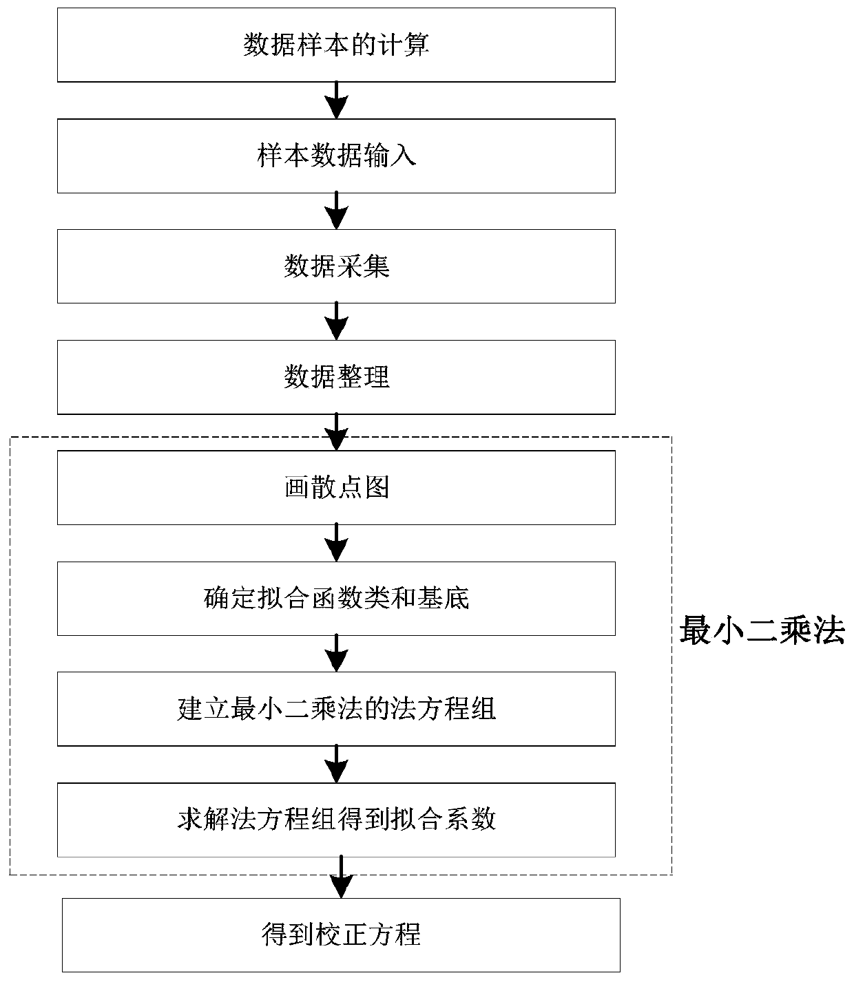
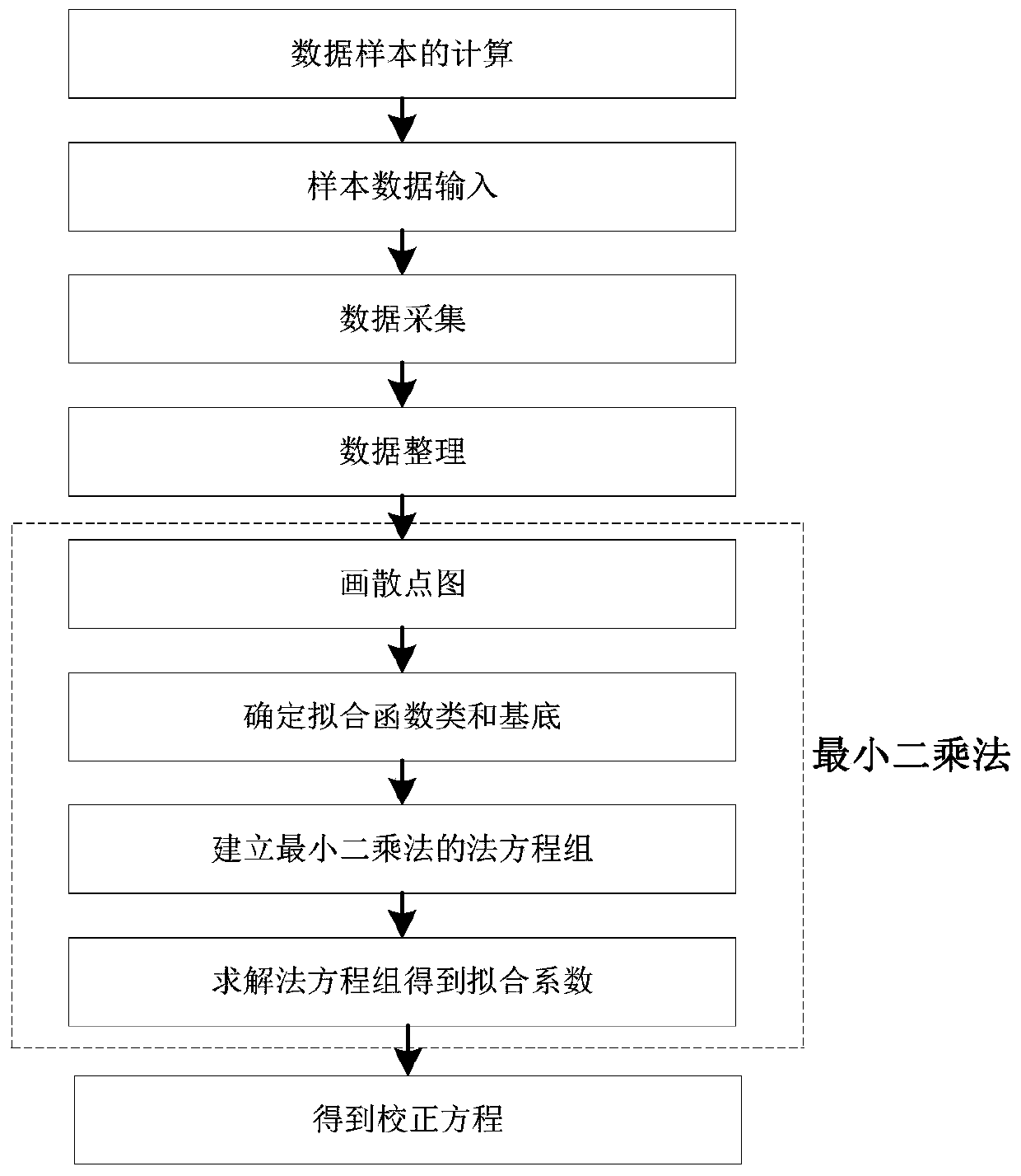
[0054] Such as figure 1 As shown, a voltage measuring device calibration method, the method includes:

[0055] Step 1: Receive the selected voltage sample value and the resistance value of the primary side of the voltage transformer;

[0056]Step 2: Calculate the current signal data according to Ohm's law, use the signal generator to generate the calculated current signal data, and input it to the input terminal of the conditioning circuit;

[0057] Step 3: receiving and storing the voltage value collected by the voltage detection device;

[0058] Step 4: Carry out one-to-one correspondence between the voltage value and the current signal data;

[0059] Step 5: According to the one-to-one correspondence between the voltage value and the current signal data, the least square method is used for correction to obtain the correcte...

Embodiment 2

[0080] According to an aspect of one or more embodiments of the present disclosure, there is provided a computer-readable storage medium.

[0081] A computer-readable storage medium, in which a plurality of instructions are stored, and the instructions are suitable for being loaded by a processor of a terminal device and executing the method for calibrating a voltage measuring device.

Embodiment 3

[0083] According to an aspect of one or more embodiments of the present disclosure, a terminal device is provided.

[0084] A terminal device, which includes a processor and a computer-readable storage medium, the processor is used to implement instructions; the computer-readable storage medium is used to store multiple instructions, and the instructions are suitable for being loaded by the processor and executing the described one A method for calibrating a voltage measuring device.

[0085] These computer-executable instructions, when executed in a device, cause the device to perform the methods or processes described in accordance with various embodiments in the present disclosure.

[0086] In this embodiment, a computer program product may include a computer-readable storage medium carrying computer-readable program instructions for performing various aspects of the present disclosure. A computer readable storage medium may be a tangible device that can retain and store i...


PUM


Abstract

The invention discloses a voltage measurement device correction method, device and system. The method comprises the following steps: receiving a selected voltage sample value and a resistance value ofa primary side of a voltage transformer; performing calculation according to the Ohm's law to obtain current signal data, so that a signal generator generates the calculated current signal data, andinputting the current signal data to an input end of a conditioning circuit; receiving a voltage value collected by a voltage detection device and storing the voltage value; performing one-to-one correspondence on the voltage value and the current signal data; and performing correction by using a least square method according to the one-to-one corresponding voltage value and the current signal data to obtain a corrected voltage value.

Description

technical field [0001] The disclosure belongs to the technical field of voltage measurement, and relates to a calibration method, device and system for a voltage measurement device. Background technique [0002] The statements in this section merely provide background information related to the present disclosure and do not necessarily constitute prior art. [0003] At present, the general principle of the voltage measurement device is that the live wire and the neutral wire are connected to the two terminals of the voltage transformer. After the voltage signal passes through the voltage transformer, the large voltage signal is converted into a small milliampere-level AC current signal, which can be received by the microcontroller. It is a DC signal between 0 and 3.3V, so the AC circuit is raised to a signal between 0 and 3.3V after the conditioning circuit. The signal at this time is converted into a digital signal between 0 and 4096 after being sampled by a 12-bit single-...

Claims


Application Information

Patent Timeline
Patent Type & Authority Applications(China)
IPC IPC(8): G01R35/00
CPCG01R35/005
Inventor 曲杰辉田崇翼张桂青王延伟袁银雪王有银陈浩任飞
Owner SHANDONG JIANZHU UNIV
Learn More