


Quick Research
Generate reliable direction feasibility study reports for your R&D in just a few steps.

Technical Q&A
Discover and master advanced knowledge NOW. Basics, ideas, possibilities, all at once.

Find Solutions
As an expert in R&D theories, this can generate solutions to your technical problems instantly.

Evaluate Feasibility
Analyze your overall solution with one click, know your potential R&D risks in advance.

Monitor Landscape
Get weekly tech updates, stay abreast of the latest tech innovations and key insights.
Liquid crystal module automatic code spraying device and control method thereof
A liquid crystal module and coding technology, applied in printing devices, printing, typewriters, etc., can solve the problem of relying on manual correction of workpiece placement, avoiding the phenomenon of batch coding of defective products, saving labor costs, and low cost. Effect
- Summary
- Abstract
- Description
- Claims
- Application Information
AI Technical Summary
Problems solved by technology
Method used
Image

Examples
Embodiment 1
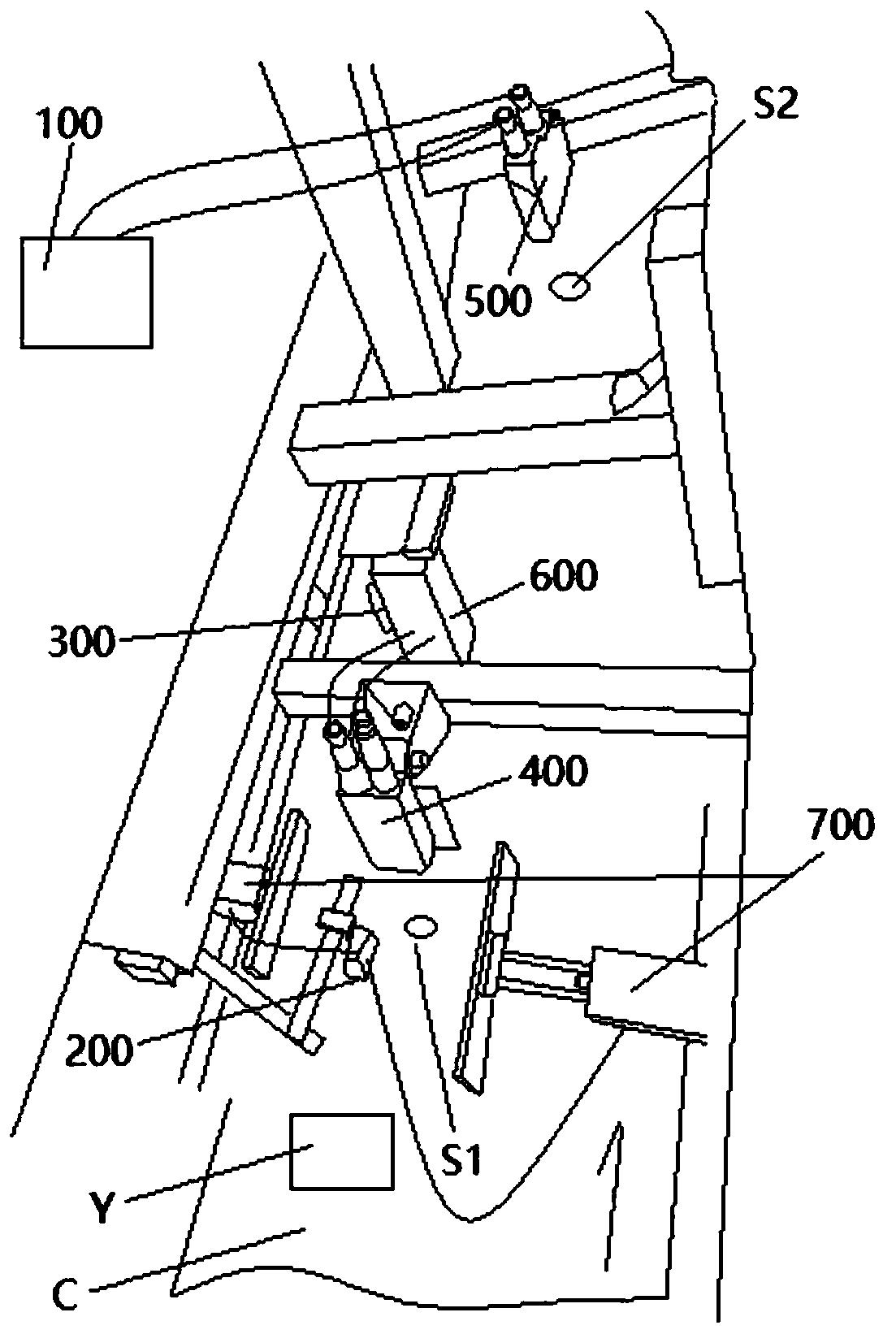
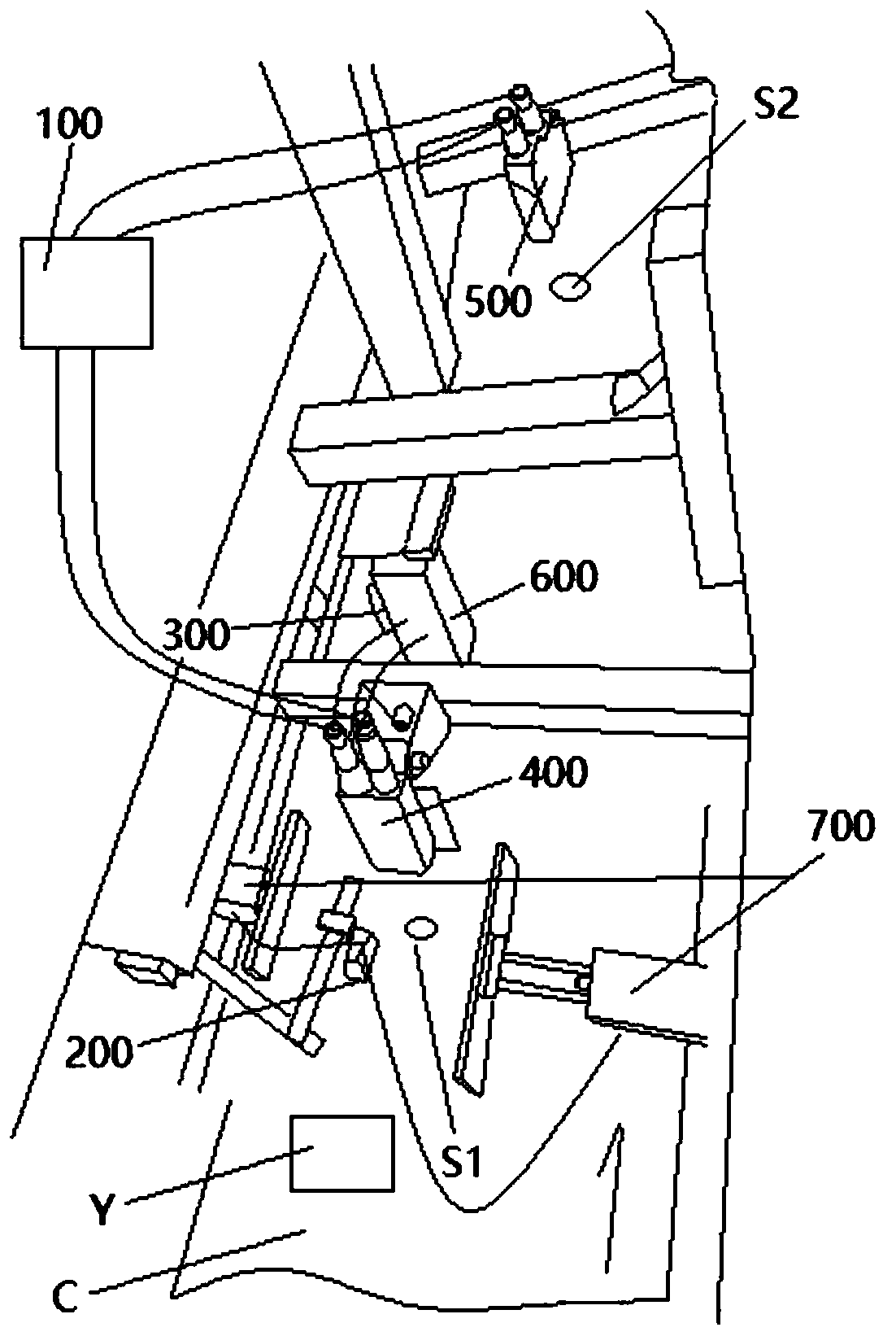
[0050] See figure 1 , the present invention provides a liquid crystal module automatic inkjet device comprising: a controller 100, a first sensor 200, a second sensor 300, a first visual reader 400, a second visual reader 500 and an inkjet printer 600; It also includes a workpiece automatic alignment mechanism 700; the first sensor 200 is electrically connected to the workpiece automatic alignment mechanism 700; the first visual reader 400 is electrically connected to the inkjet printer 600; the second The sensor 300 is electrically connected to the second visual reader 500; the second visual reader 500 is electrically connected to the controller 100; the first sensor 200 is used to trigger the workpiece automatic alignment mechanism 700 Action; the execution end 710 of the workpiece automatic alignment mechanism 700 is used to adjust the placement position of the liquid crystal module Y on the conveyor belt C; the first visual reader 400 is used to identify the workpiece in t...
Embodiment 2
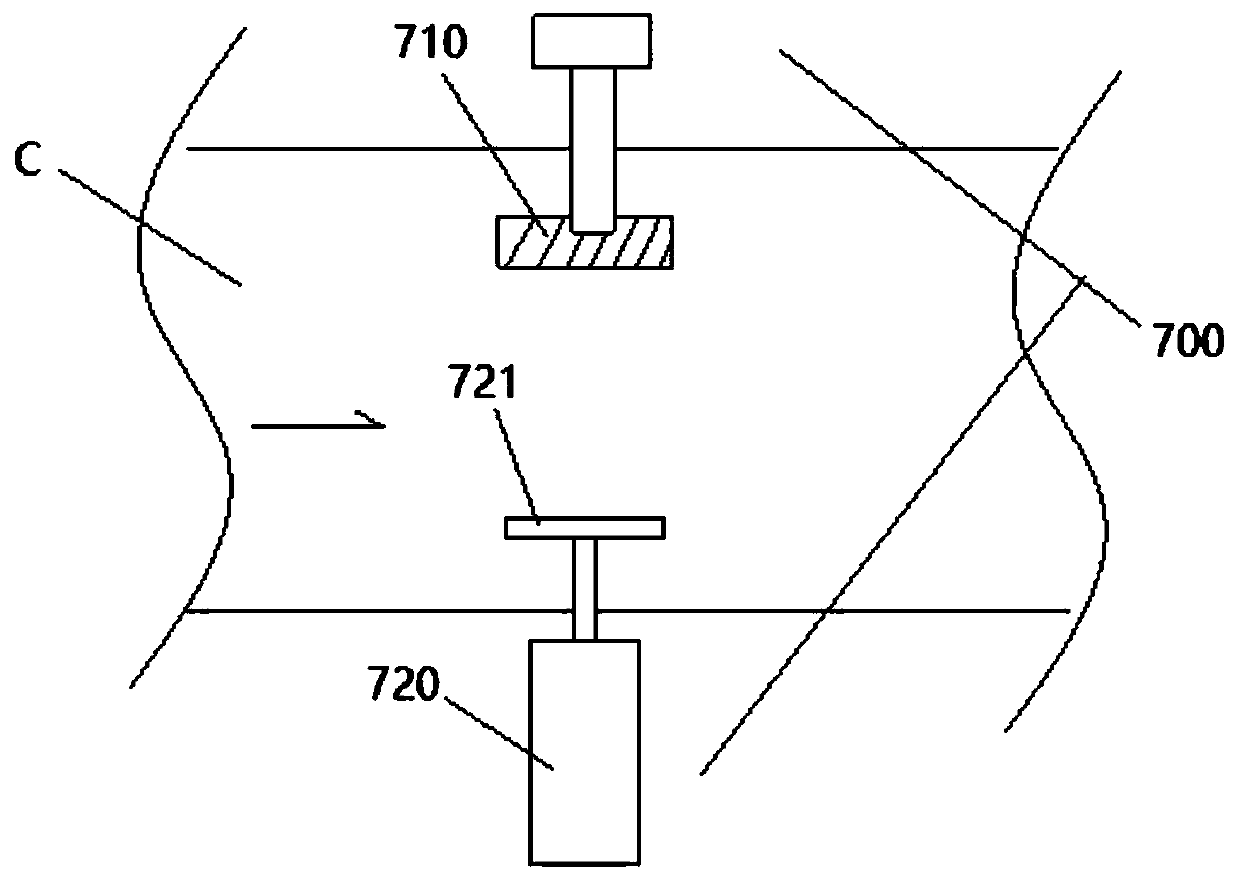
[0060] Such as image 3 As shown, in this embodiment, the workpiece automatic alignment mechanism 700 includes: a master form 710 and a cylinder 720 that is arranged on the opposite side of the form 710 and has a push plate 721 at its free end; the master form 710 and the cylinder 720 Said air cylinder 720 is oppositely arranged on both sides of the conveyer belt perpendicular to the conveying direction; said air cylinder acts to clamp said workpiece between said former and said push plate, and said workpiece completes position alignment; The position alignment is satisfied: when the workpiece passes directly under the nozzle of the inkjet printer, the part of the workpiece to be coded is relatively positive to the spraying position of the nozzle of the inkjet printer. The workpiece automatic alignment mechanism that matches the profile and the cylinder is used, and the liquid crystal module that can place the upstream station on the assembly line can automatically correct the...
Embodiment 4
[0066] This embodiment provides on the basis of the foregoing embodiments, a method for controlling an automatic coding device for a liquid crystal module, the method comprising the following steps:
[0067] The first sensor recognizes that the liquid crystal module has reached the executable area of the workpiece automatic alignment mechanism;
[0068] The automatic workpiece alignment mechanism operates to adjust the placement position of the liquid crystal module on the conveyor belt to a uniform setting position;
[0069] After the first visual reader recognizes that the position of the liquid crystal module is aligned, it sends an action trigger signal to the inkjet printer;
[0070] The inkjet printer operates the inkjet code after obtaining the action trigger signal;
[0071] When the second sensor recognizes that the liquid crystal module arrives at the recognizable area of the second visual reader, it sends a trigger signal for inkjet reading to the second visual...
PUM
 Abstract
Description
Claims
Application Information
 - R&D Engineer
- R&D Manager
- IP Professional
- Industry Leading Data Capabilities
- Powerful AI technology
- Patent DNA Extraction
Browse by: Latest US Patents, China's latest patents, Technical Efficacy Thesaurus, Application Domain, Technology Topic, Popular Technical Reports.
© 2024 PatSnap. All rights reserved.Legal|Privacy policy|Modern Slavery Act Transparency Statement|Sitemap|About US| Contact US: help@patsnap.com