Hot forging die upper die with internal cooling function and cooling method thereof

A hot forging die and functional technology, applied in heating/cooling equipment, manufacturing tools, forging/pressing/hammer devices, etc., can solve the problems of reducing die life, pollution of workshop working environment, and ejection force of die and forging bonding , to achieve sufficient cooling, improve manufacturability, and improve the effect of mold life

Active Publication Date: 2019-07-16
安徽康尼精密机械有限公司
View PDF6 Cites 2 Cited by
  • Summary
  • Abstract
  • Description
  • Claims
  • Application Information

AI Technical Summary

Problems solved by technology

The disadvantage of this lubrication method is that a large amount of graphite vapor will be generated, which will cause environmental pollution in the workshop
In the hot forging form with a large amount of water, the mold does not need to be heated, but it needs to be cooled in time to keep the mold at room temperature during the production process, and the residual water on the surface of the mold during rapid forming is instantly vaporized into water vapor for lubrication. In time, the die and forging will have a phenomenon of bonding and a sharp increase in ejection force, which greatly reduces the life of the die, and sometimes even causes the product to fail to form. Therefore, it is necessary to cool in the lower die and upper die in time.

Method used


Image

  • Hot forging die upper die with internal cooling function and cooling method thereof
  • Hot forging die upper die with internal cooling function and cooling method thereof
  • Hot forging die upper die with internal cooling function and cooling method thereof

Examples


Embodiment Construction

[0039] The present invention will be further explained below in conjunction with the accompanying drawings and specific embodiments. It should be understood that the following specific embodiments are only used to illustrate the present invention but not to limit the scope of the present invention.

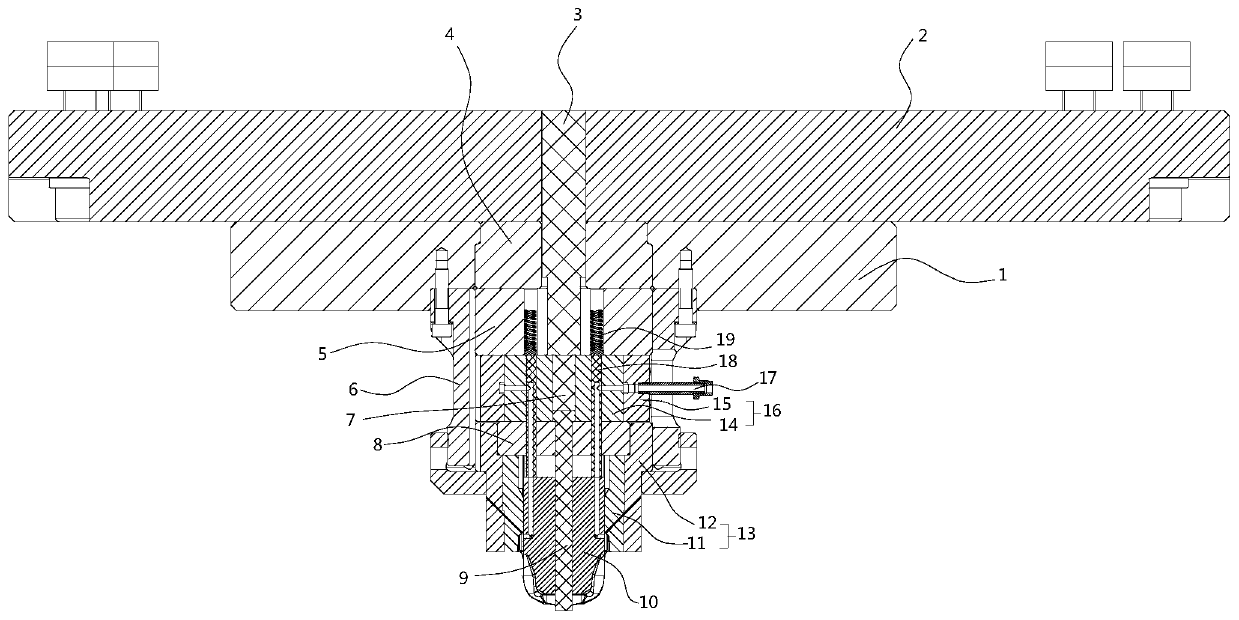
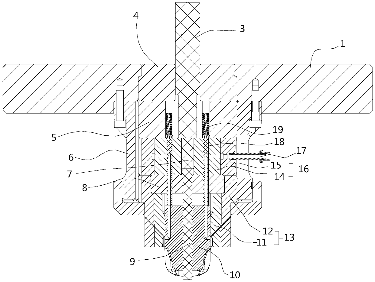
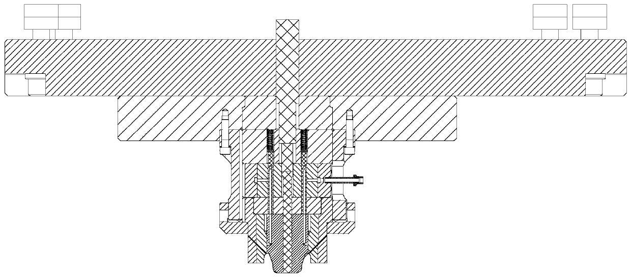
[0040] figure 1 It is a schematic diagram of the working state of the upper mold internal cooling system of the upper mold of the present invention, figure 2 yes figure 1The enlarged view after removing the upper backing plate, combined with these two figures, it can be seen that the upper die of the present invention is equipped with a mold frame system, a feeding mechanism, a punch assembly, a punch support pad system and a punch internal cooling system. The formwork system includes a horizontally arranged upper backing plate 2 , the lower surface of the upper backing plate 2 is closely fixed with an upper formwork 1 , and the upper formwork 1 and the upper backing plate 2 ar...


PUM


Abstract

The invention discloses a hot forging die upper die with an internal cooling function and a cooling method thereof. The hot forging die upper die comprises a die frame system, a material beating mechanism is vertically arranged in the die frame system, a punch assembly is arranged at the lower end of the material beating mechanism, the material beating mechanism is arranged in the die frame systemthrough a supporting cushion block system, the material beating mechanism drives the punch assembly to move vertically in the die frame system synchronously, after the material beating mechanism descends, a hot forging piece on a punch hot forging lower die frame, an upper die inner cooling system is arranged in the supporting cushion block system, and the upper die inner cooling system and the punch assembly are synchronously lifted. When the method is in the die closing state of the hot forging die, the upper die inner cooling system does not work, the upper die moves upwards, the upper dieinner cooling system works, and a flowing cooling water environment, a cooling punch assembly, the supporting cushion block system and the material beating mechanism are formed around the punch assembly.

Description

technical field [0001] The invention relates to an upper mold of a hot forging die with an internal cooling function and a cooling method thereof, belonging to the technical field of hot forging cooling. Background technique [0002] In traditional hot forging, the mold needs to be heated to about 200°C, and the mold is lubricated by spraying graphite suspension on the surface of the mold. After evaporation, the residual graphite acts as a lubricating medium at high temperature. The disadvantage of this lubrication method is that a large amount of graphite vapor will be generated, which will cause environmental pollution in the workshop. In the hot forging form with a large amount of water, the mold does not need to be heated, but it needs to be cooled in time to keep the mold at room temperature during the production process, and the residual water on the surface of the mold during rapid forming is instantly vaporized into water vapor for lubrication. In time, the die and ...

Claims


Application Information

Patent Timeline
Patent Type & Authority Applications(China)
IPC IPC(8): B21J13/02B21J13/14B21K29/00
CPCB21J13/02B21J13/14B21K29/00
Inventor 袁天宇
Owner 安徽康尼精密机械有限公司
Why Eureka
Try Eureka