
Design Method of Vertical Fin Tube Heat Exchanger

A heat exchanger and fin-and-tube technology, which is applied in the field of waste heat removal from fast reactor accidents, can solve problems such as failure to meet design requirements, and achieve the effect of reliable theoretical basis

Active Publication Date: 2021-06-25
CHINA INSTITUTE OF ATOMIC ENERGY
View PDF8 Cites 0 Cited by
  • Summary
  • Abstract
  • Description
  • Claims
  • Application Information

AI Technical Summary

Problems solved by technology

Through the demonstration and analysis of air heat exchangers with existing structural forms such as vertical smooth tube, serpentine finned tube and smooth tube spiral tube, it can be seen that these tube structures are far from meeting the above design requirements

Method used


Image

  • Design Method of Vertical Fin Tube Heat Exchanger
  • Design Method of Vertical Fin Tube Heat Exchanger
  • Design Method of Vertical Fin Tube Heat Exchanger

Examples


Embodiment Construction

[0084] In order to make the purpose, technical solution and advantages of the present invention clearer, the technical solution of the present invention will be clearly and completely described below in conjunction with the accompanying drawings of the embodiments of the present invention. Apparently, the described embodiment is one embodiment of the present invention, but not all of them. Based on the described embodiments of the present invention, all other embodiments obtained by persons of ordinary skill in the art without creative efforts shall fall within the protection scope of the present invention.

[0085] Unless otherwise defined, the technical terms or scientific terms used in the present invention shall have the usual meanings understood by those skilled in the art to which the present invention belongs.

[0086] The vertical fin tube heat exchanger is very different from the traditional heat exchanger. The angle at which the air scours the heat exchange tube vari...


PUM


Abstract

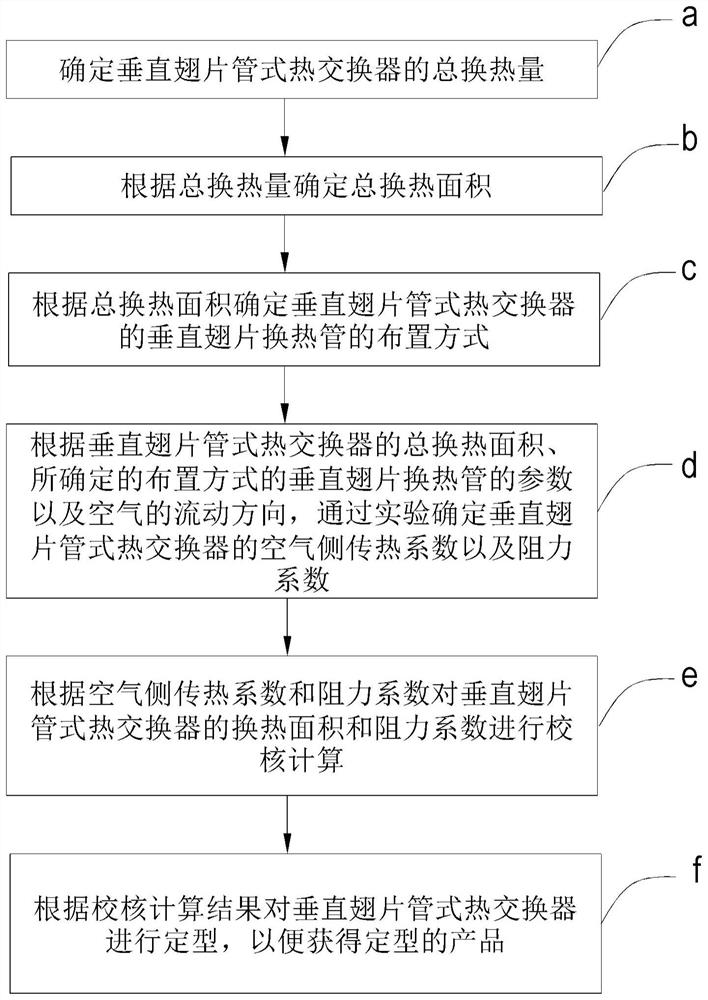
The present invention provides a design method of a vertical finned tube heat exchanger, the design method comprising the following steps: a. determining the total heat transfer capacity of the vertical finned tube heat exchanger; b. according to the total Determine the total heat exchange area for the amount of heat exchange; c. determine the arrangement of the vertical fin heat exchange tubes of the vertical fin tube heat exchanger according to the total heat exchange area; d. The total heat exchange area of ​​the heat exchanger, the parameters of the determined arrangement of the vertical fin heat exchange tubes and the flow direction of the air, and the air side heat transfer coefficient and resistance of the vertical fin tube heat exchanger are determined through experiments Coefficient; e. check and calculate the heat transfer area and resistance coefficient of the vertical fin tube heat exchanger according to the air side heat transfer coefficient and the resistance coefficient; and f. according to the check calculation result The vertical finned tube heat exchanger is shaped in order to obtain a shaped product.

Description

technical field [0001] The invention relates to the field of fast reactor accident waste heat discharge, and more specifically, relates to a design method of an air heat exchanger. Background technique [0002] At present, the basic principle of passive waste heat removal is natural circulation, that is, the use of fluid gravity, inertia, natural convection, diffusion, evaporation, condensation and other principles to remove waste heat from the core under accident conditions. The setting of the corresponding system can simplify the special safety facilities, reduce equipment and components, reduce possible misoperations caused by personnel intervention, improve the relationship between man and machine, and improve the inherent safety of nuclear power plants. Therefore, technically speaking, passive technology is an advanced safety technology at present and represents the development trend of a new generation of nuclear power. [0003] In order to meet the passive requiremen...

Claims


Application Information

Patent Timeline
Patent Type & Authority Patents(China)
IPC IPC(8): G06F30/28G06F113/08G06F119/14G06F119/08
CPCG06F30/17G06F2119/08
Inventor 朱丽娜叶原武杨红义申凤阳余华金宋广懂武志广龚雪婷侯斌杜丽岩
Owner CHINA INSTITUTE OF ATOMIC ENERGY
Learn More