Optical lens module and forming method thereof

An optical lens and module technology, applied in the optical field, can solve problems such as damage to the collected objects, and achieve the effect of optimizing the structure

Inactive Publication Date: 2019-07-12
HOWE OPTOELECTRONICS TECH SHANGHAI
View PDF8 Cites 0 Cited by
  • Summary
  • Abstract
  • Description
  • Claims
  • Application Information

AI Technical Summary

Problems solved by technology

In face recognition equipment, the image acquisition unit of the equipment captures images of the captured object under the irradiation of the laser source through the optical lens module. However, when the glass substrate of the optical lens module is damaged, the laser source emits The laser will shoot out from the damaged part and directly irradiate the collected object (usually a person), causing the collected object to be damaged by the laser
[0003] In order to solve this problem, an ITO film layer is formed on the side of the glass substrate facing away from the optical glue. The ITO film layer enables the control system of the face recognition equipment to detect whether the glass substrate of the optical lens module is damaged, and then Turn off the laser source when the glass substrate is damaged, so as to avoid the laser emitted by the laser source from causing damage to the object to be collected. However, this structure has limitations

Method used


Image

  • Optical lens module and forming method thereof
  • Optical lens module and forming method thereof
  • Optical lens module and forming method thereof

Examples


Embodiment Construction

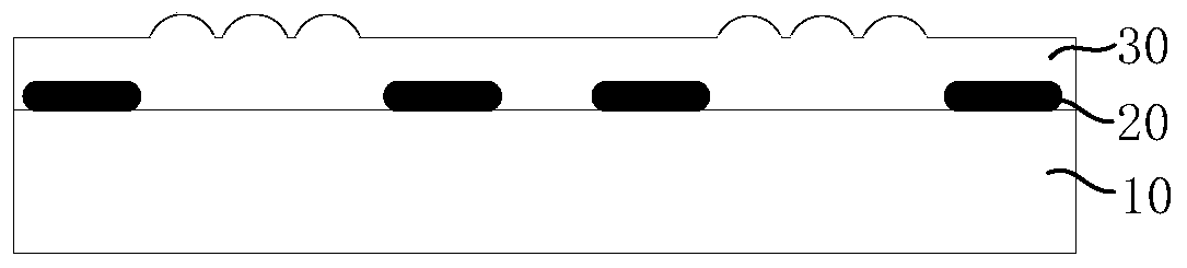
[0040] As described in the background art, there is a limitation in forming an ITO film on the side of the glass substrate facing away from the optical glue. Therefore, the inventors set the ITO film on the side of the glass substrate facing the optical glue and used the following method Prepare wafer-level optical lens (WLO), as follows: figure 1 As shown, first, a circular glass substrate 10 is provided. An ITO film layer is formed on the glass substrate 10, and the ITO film layer includes at least two ITO pads 20; then, on the glass substrate 10 The side with the ITO film layer is covered with a layer of optical glue 30; then, the optical glue 30 is pressed by a mold; then, the optical glue 30 is cured by UV (ultraviolet light) and / or thermally baked 30 Perform curing treatment; finally, remove the mold. Since all the optical lens modules of the wafer-level optical lens in the above process are prepared through an integrated molding process, the ITO film is completely confin...


PUM


Abstract

The invention discloses an optical lens module and a forming method thereof, and the method comprises the following steps: providing a substrate which is provided with a first surface and a second surface opposite to the first surface, forming an intermediate film layer on the first surface, enabling the intermediate film layer to partially cover the first surface of the substrate, and enabling the intermediate film layer to at least comprise a leading-out unit; and forming an optical adhesive on the substrate and the intermediate film layer, the optical adhesive having a groove, the bottom ofthe groove exposing at least a portion of the lead-out unit. According to the invention, the intermediate film layer can be formed between the optical cement and the substrate, so that whether the substrate of the optical lens module is damaged can be detected, and the structure of the optical lens module is optimized.

Description

Technical field [0001] The present invention relates to the field of optics technology, in particular to an optical lens module and a forming method thereof. Background technique [0002] With the rapid development of imaging technology, optical lens modules are widely used in various fields, such as digital cameras, smart phones and other fields, as well as the rapidly developing face recognition field in recent years. In the face recognition equipment, the image acquisition unit of the equipment uses the optical lens module to capture the image of the collected object under the irradiation of the laser source. However, when the glass substrate of the optical lens module is damaged, the laser source emits The laser will shoot out from the damage and directly irradiate the collected object (usually a person), causing the collected object to be damaged by the laser. [0003] In order to solve this problem, an ITO film layer is formed on the side of the glass substrate facing away f...

Claims


Application Information

Patent Timeline
IPC IPC(8): G02B3/00
CPCG02B3/0031
Inventor 李绍志仇爱刚林桂锋
Owner HOWE OPTOELECTRONICS TECH SHANGHAI
Why Eureka
Try Eureka